A request for 300 meters of electromagnetic survey depth can appear straightforward in a scope of work. It is not. Electromagnetic survey depth is a performance outcome governed by subsurface conductivity, target geometry, transmitter energy, sensor configuration, noise conditions, and the threshold used to define a usable response. Treating depth as a fixed equipment specification is a common source of mismatched expectations, incomplete target definition, and non-defensible exploration decisions.
For mining, groundwater, infrastructure, and energy projects, the relevant question is not simply, "How deep can the system see?" It is: at what depth can the selected survey system detect, resolve, and characterize the geological feature that matters to the project?
Electromagnetic Survey Depth Is Not a Single Number
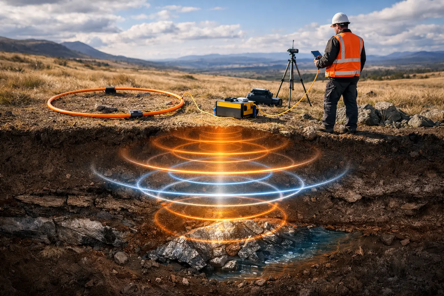
Electromagnetic methods induce or measure electrical fields associated with conductive materials in the ground. The resulting response weakens with depth, but it does not weaken at a uniform rate. A shallow conductive clay layer can mask a deeper conductor. A highly conductive sulfide body may remain detectable well below the nominal depth of investigation. A resistive host rock can permit greater penetration but may produce little contrast unless the target itself is conductive.
This distinction matters because detection, delineation, and interpretation are different performance levels. A system may detect evidence of a conductor at depth without resolving its thickness, dip, conductivity, or boundaries. Engineering and resource decisions generally require more than a weak anomaly. They require an interpreted model with uncertainty limits that can be cross-validated against geology, boreholes, other geophysical datasets, or follow-up ground work.
Depth of investigation should therefore be reported as a range tied to stated assumptions, not as an unconditional maximum. A defensible technical proposal identifies the target type, expected conductivity contrast, host conditions, flight or line geometry, and minimum response confidence required for the decision at hand.
What Controls Electromagnetic Survey Depth?
Conductivity contrast and host geology
Conductivity contrast is usually the dominant variable. Electromagnetic systems respond to contrasts in electrical conductivity, not to depth alone. A conductive aquifer in a resistive formation may be mapped effectively at a meaningful depth. The same aquifer beneath conductive alluvium or saline overburden may be difficult to separate, even if the system's theoretical penetration is greater.
In mineral exploration, massive sulfides, graphite, saline groundwater, clay alteration, and conductive overburden can all generate significant responses. Their signatures may overlap. Interpretation must determine whether an anomaly represents the intended target, near-surface material, cultural interference, or a combination of effects. In arid environments, dry resistive surface materials can favor penetration, while saline zones, playa sediments, and conductive weathered horizons can sharply reduce target visibility.
Target geometry also changes the result. A steeply dipping conductor aligned favorably with the transmitter-receiver geometry can produce a strong response. A thin, flat-lying, or laterally limited target at the same depth may not. Survey planning must be built around the expected geological model rather than a generic depth claim.
Transmitter moment, frequency, and timing
System design controls how much energy enters the ground and which conductivity ranges are emphasized. In time-domain electromagnetic surveys, a larger transmitter moment and later-time measurements can support investigation of deeper conductive features. However, later-time data are also weaker and more susceptible to noise. Increasing transmitter power does not automatically create useful depth if the survey environment or receiver sensitivity limits the signal-to-noise ratio.
Frequency-domain systems use multiple frequencies to characterize shallow to intermediate-depth conductivity structure. Lower frequencies commonly investigate deeper than higher frequencies, but the practical result depends on coil spacing, altitude, terrain clearance, and local geology. A broad frequency range can improve layer discrimination, yet it cannot compensate for poor survey geometry or severe cultural noise.
For airborne and drone-based electromagnetic surveys, low and stable terrain clearance is operationally valuable because signal strength decreases rapidly as the sensor moves farther from the ground. That advantage must be balanced against terrain, obstacles, flight safety, payload limitations, and the need to maintain consistent acquisition conditions. The best flight altitude is not simply the lowest achievable altitude. It is the altitude that delivers safe, repeatable, calibrated data across the planned survey area.
Noise, interference, and data quality
Depth claims fail when noise is ignored. Powerlines, pipelines, fences, rail infrastructure, active industrial facilities, radio-frequency interference, vibration, altitude variation, and sensor drift can distort weak electromagnetic responses. Deep targets are especially vulnerable because their signals are often close to the survey noise floor.
Quality assurance must start before mobilization. It includes system calibration, base checks where applicable, line planning, terrain assessment, test lines, repeat lines, and clear acceptance criteria for positioning, altitude, sensor behavior, and noise levels. During processing, filtering must be controlled and traceable. Excessive smoothing may make data appear cleaner while removing the subtle responses that justify a deeper interpretation.
Designing for the Required Electromagnetic Survey Depth
A disciplined survey begins with a target-depth objective, then works backward to select the method and acquisition parameters. For example, a groundwater program may need to distinguish conductive saline water from fresher water-bearing zones within fractured bedrock. That objective requires consideration of lithology, expected salinity, depth to bedrock, borehole control, and the need to separate vertical changes in conductivity from lateral changes in geology.
A mineral program may instead seek discrete conductors below transported cover. In that case, line spacing, transmitter geometry, terrain clearance, late-time signal quality, and integration with magnetic or radiometric data can carry more value than a broad but weak depth estimate. The survey should be designed to improve target discrimination, not merely maximize a theoretical investigation depth.
A practical design review should establish four conditions before acquisition:
- The geological target and its expected conductivity signature are defined from available mapping, drilling, samples, or nearby analogs.
- The required decision depth is separated from the preferred exploration depth, so scope and risk can be priced realistically.
- The selected platform, sensor, line spacing, altitude, and acquisition parameters are tested against terrain and access constraints.
- The final deliverables specify how depth sensitivity, uncertainty, anomalies, and processing decisions will be documented.
This approach allows project owners to compare proposals on technical suitability rather than headline depth. It also prevents a common error: collecting regional reconnaissance data and expecting it to provide drill-target resolution.
Method Selection Changes the Depth Answer
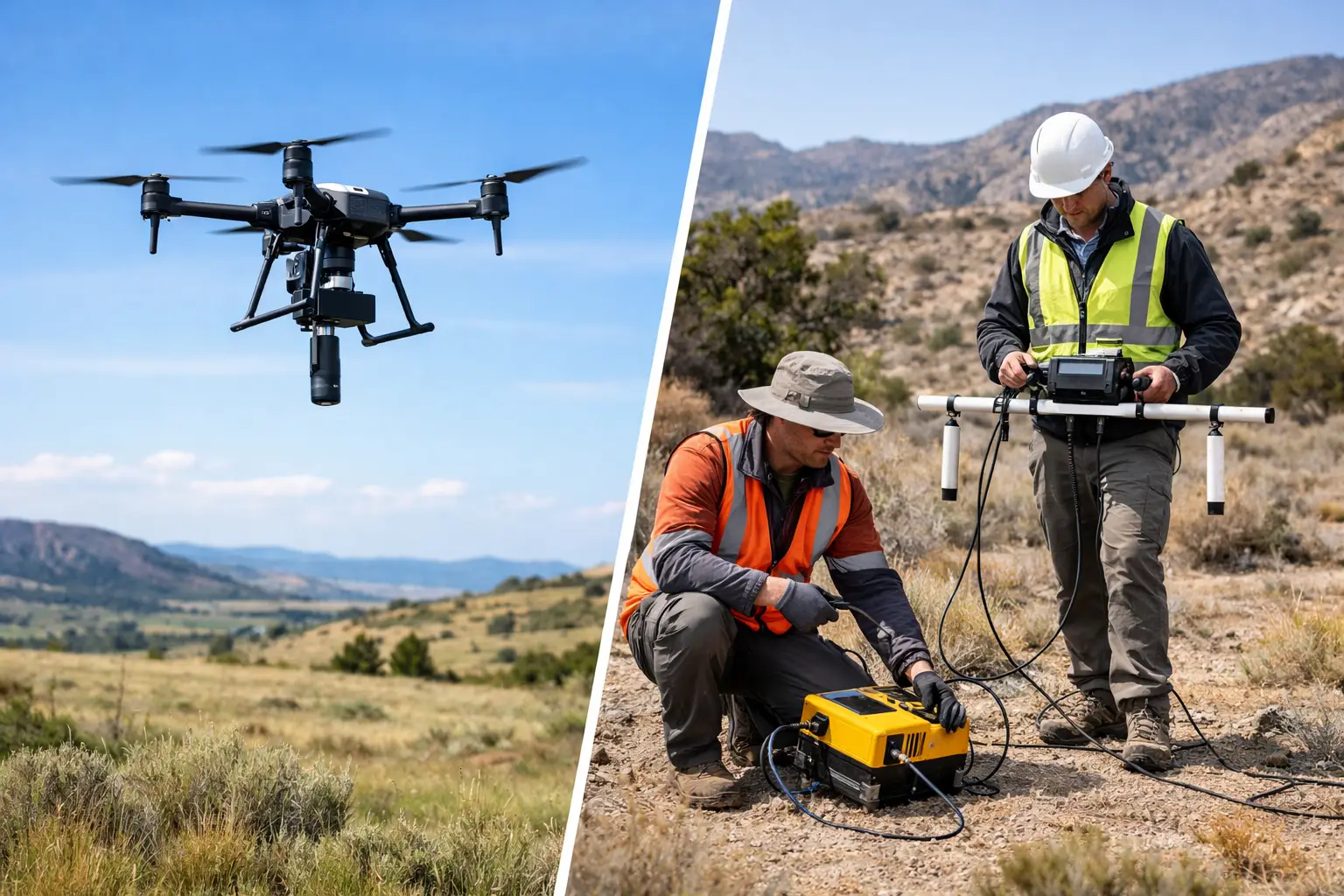
Airborne electromagnetic systems can cover large areas rapidly and identify regional conductivity patterns, conductive corridors, and prospective targets that would be slow to map from the ground. Drone deployment can add flexibility where access is restricted, terrain is difficult, or rapid mobilization is required. Its value is strongest when survey parameters, flight control, and data processing are engineered for the local target model.
Ground electromagnetic methods may provide tighter control over station spacing, transmitter geometry, and localized follow-up. They can be appropriate where detailed resolution is needed over a limited footprint or where airborne operations are constrained. The trade-off is slower coverage, more field exposure, and reduced efficiency across broad terrain.
Other methods can reduce ambiguity. Aeromagnetic data may define structures, lithological boundaries, and intrusive bodies that explain electromagnetic anomalies. LiDAR and photogrammetry improve terrain control and line-planning confidence. Borehole logs, hydrogeological data, and geological mapping remain essential for converting conductivity models into decisions about water, mineralization, excavation risk, or utility corridors.
Reporting Depth With Decision-Grade Discipline
A credible interpretation does not state that a target is at an exact depth without explaining the model basis. Electromagnetic inversion estimates a conductivity distribution that is influenced by data coverage, noise, regularization choices, starting models, and geological constraints. Different models may fit the data similarly, particularly at depth.
Technical reporting should distinguish measured data from interpreted outputs. It should document acquisition parameters, calibration records, line statistics, repeatability checks, processing workflow, inversion settings, depth-sensitivity limits, and areas where cultural interference or terrain reduced confidence. Where possible, interpretation should be cross-validated against drilling, surface geology, ground geophysics, or independent sensor datasets.
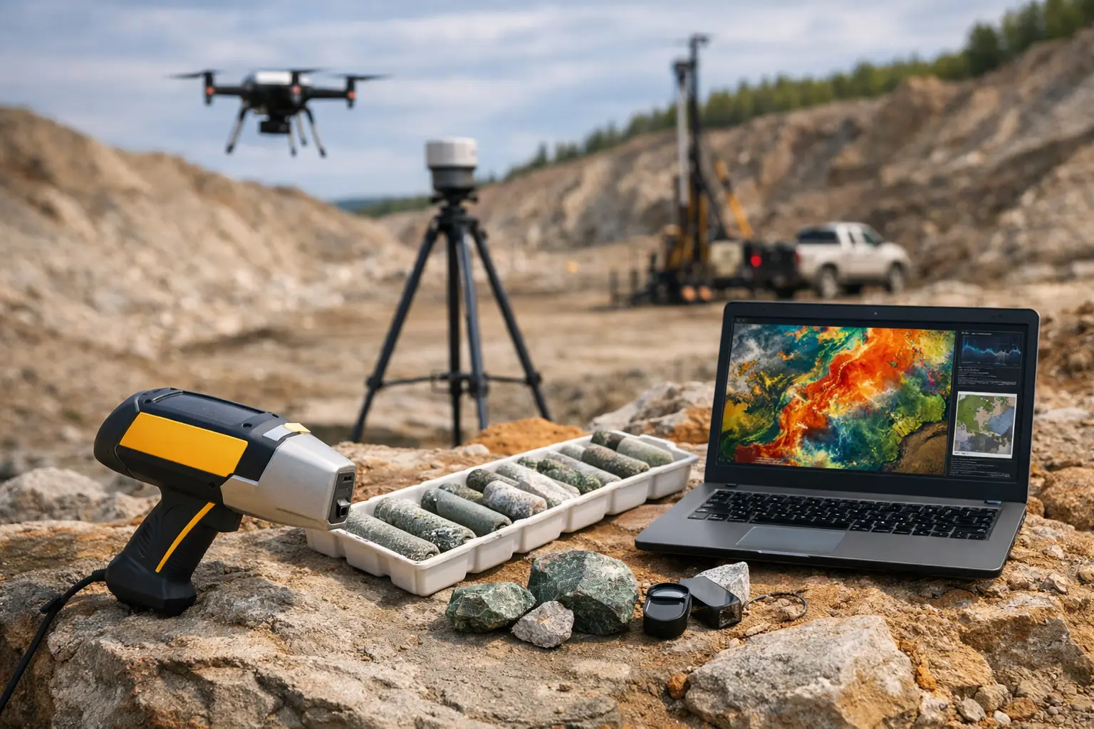
For high-value projects, the deliverable is not a colored conductivity image. It is an auditable geospatial intelligence package that states what the data support, where uncertainty remains, and what action should follow. That may mean defining a drill target, narrowing a groundwater exploration area, redesigning a follow-up survey, or ruling out a target concept before additional capital is committed.
The most useful depth target is the one tied to a real decision. Define that decision early, design the electromagnetic survey around the expected geology and operating environment, and require traceable evidence for every claim made below the surface.