Airborne EM
Resistivity.
Multi-frequency airborne electromagnetic surveys for sub-surface conductivity mapping, mineral targeting, and aquifer characterisation across arid terrain. Time-domain and frequency-domain systems imaged to 400 m depth.
- System
- Multi-frequency FDEM + TDEM
- Depth of investigation
- 0–400 m
- Sensitivity
- 1–5 Ω·m
- Line spacing
- 50–250 m
- Coverage
- ~60 km²/day
Sub-surface conductivity at survey speed.
Airborne EM is the workhorse method for mapping sub-surface conductivity over wide areas — aquifer characterisation, conductive ore-body targeting, regolith and salinity mapping, and structural interpretation all rest on a high-quality EM dataset.
We operate multi-frequency frequency-domain EM and full-waveform time-domain EM platforms — selected per project objective and depth of investigation. Data are inverted using 1D LCI for rapid product delivery, then refined with 2D/3D blocky inversion where the target geometry demands it.
Output is a conductivity volume tied to your coordinate system, with vertical sections along survey lines and interpreted depth-slice maps — all ready for integration with magnetic, gravity, and geological context.
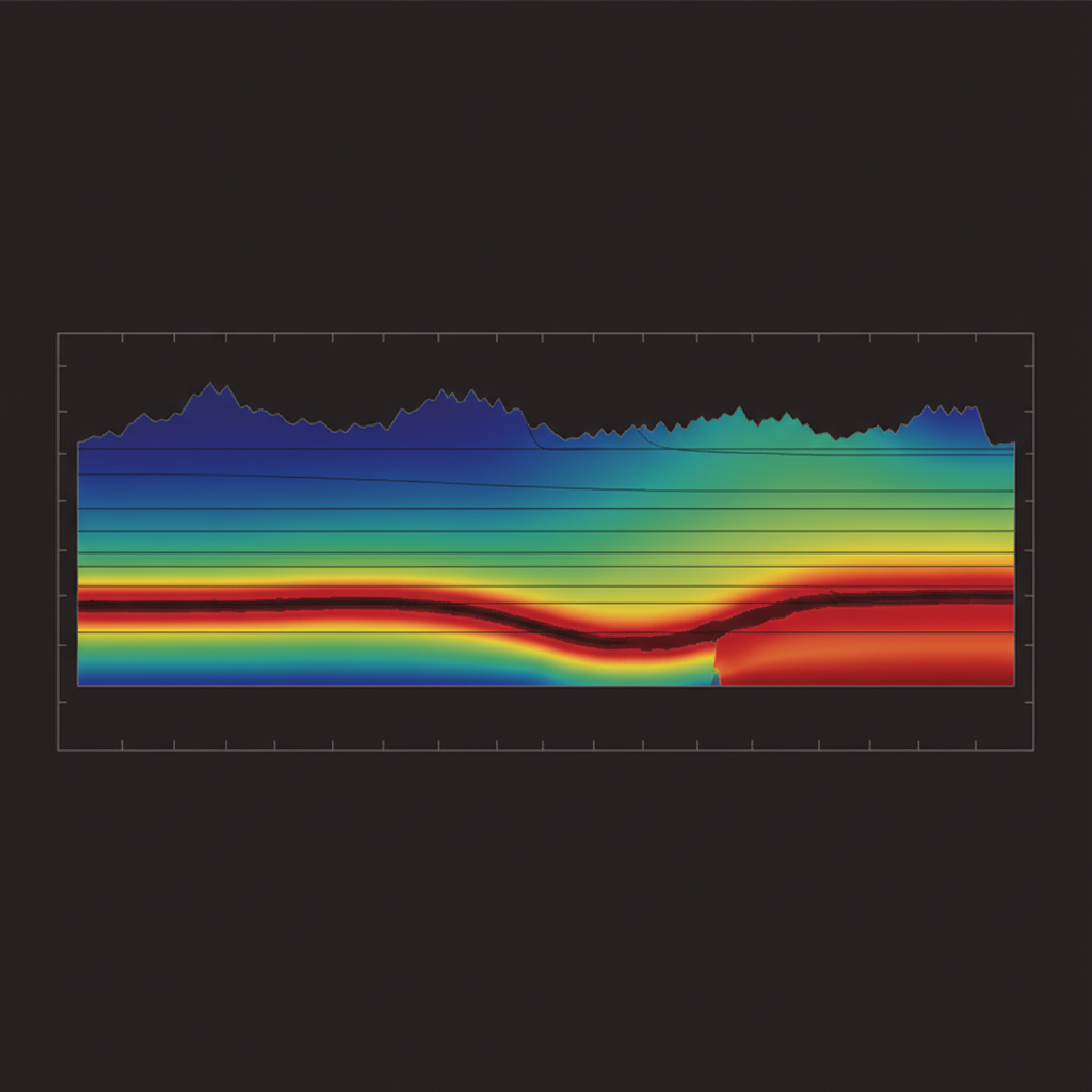
Resistivity-depth section
Laterally-constrained 1D inversion stitched into a continuous vertical section — the standard product for fast hydrogeological interpretation.
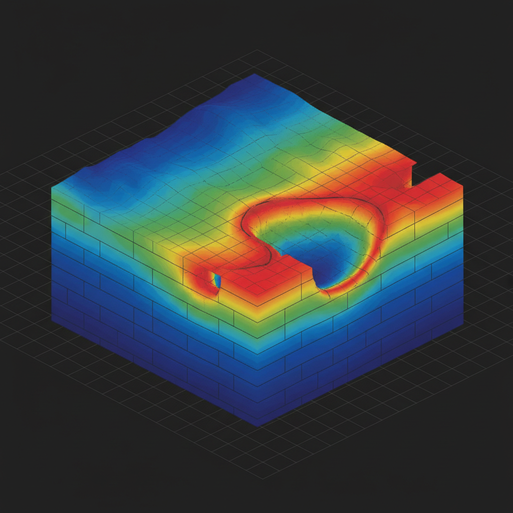
Conductivity volume
Calibration & drift removal → motion noise filter → 1D LCI inversion → conductivity volume build → 3D refinement (target zones) → depth-slice + section export.
From EM signal to conductivity model.
System Selection & Block Design
FDEM or TDEM chosen against target depth. Line spacing tuned to anomaly scale. Calibration baseline established over known conductivity.
Airborne Acquisition
Slung sensor pod flown along planned grid. Continuous calibration checks and motion-noise monitoring.
Inversion
1D laterally-constrained inversion across all lines. 2D/3D blocky inversion where target geometry requires it.
Interpretation & Report
Depth-slice maps, vertical sections, and target ranking against client geological model.
What you receive.
Conductivity volume
3D inverted conductivity to depth-of-investigation. Voxel + GeoTIFF stacks.
Vertical sections
1D LCI sections along survey lines + interpreted cross-sections.
Depth-slice maps
Conductivity-depth slices at client-specified intervals.
Target ranking
Priority-ranked conductive anomalies with rationale and coordinates.
Integrated interpretation
EM + magnetic + topo overlay with geological context.
Final report + QA/QC log
PDF report, calibration records, processing log, chain of custody.
Where this service is deployed.
Image your sub-surface.
Share your block and target depth. We respond with EM system selection, line spacing, and schedule within 48 hours.