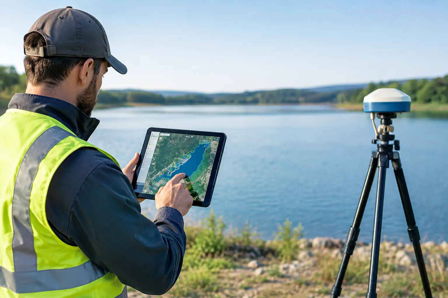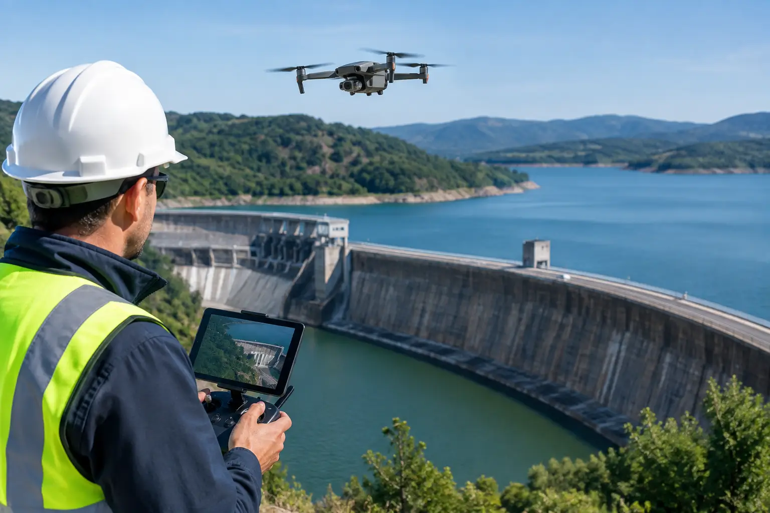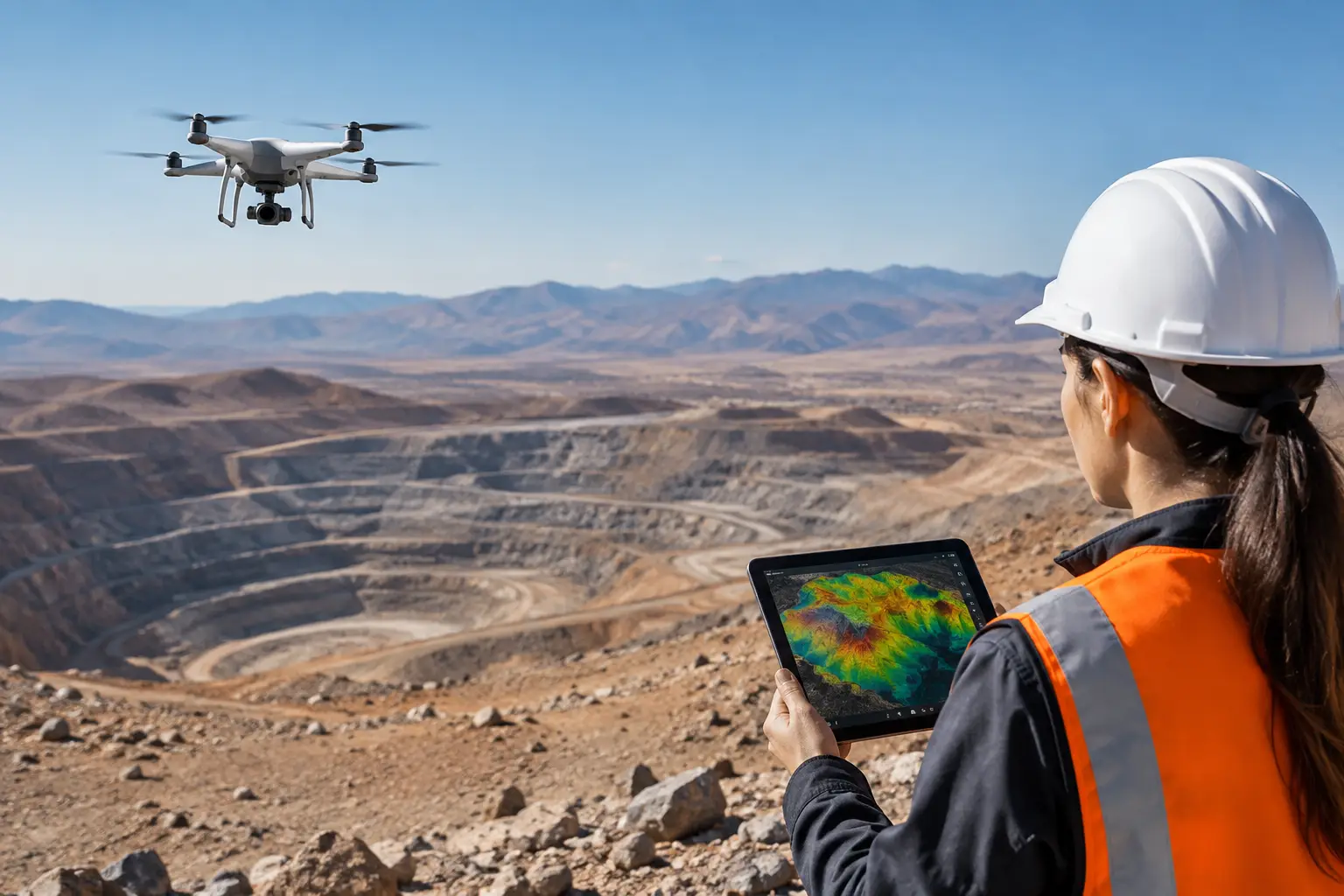
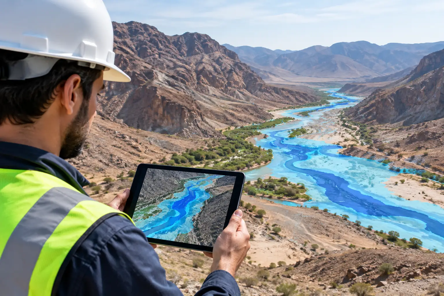
A wadi flood mapping example is most useful when it moves beyond a colored hazard map and answers an engineering question: where can an asset be placed, crossed, or protected with defensible confidence? In arid terrain, a channel that appears dry for years can convey destructive runoff during a short-duration storm. For developers, utilities, mining operators, and infrastructure planners, the operational risk is not simply water. It is uncertain flow paths, debris loading, scour, sediment deposition, and access loss across terrain that may be poorly surveyed.
Why wadi mapping requires more than a contour plan
A wadi is not a stable drainage feature. Its active flow path can widen, split, migrate, or become obstructed by sediment bars, access roads, culverts, and informal earthworks. Standard topographic mapping may identify the visible channel, but it can miss low-relief overflow routes and local controls that govern where floodwater actually concentrates.
This is particularly significant on linear infrastructure corridors. A road, pipeline, transmission route, or haul road can act as an unintended embankment. If drainage openings are undersized or positioned outside the true conveyance path, runoff may pond upstream, overtop the alignment, or cut around the structure. The resulting damage can occur far from the apparent centerline of the wadi.
Decision-grade flood mapping therefore combines calibrated terrain acquisition with hydrologic and hydraulic interpretation. The objective is to define flow behavior under stated design assumptions, document the evidence behind the result, and identify the limitations that remain. A flood extent without terrain accuracy, roughness assumptions, and model traceability is not sufficient for capital planning or design review.
Wadi flood mapping example: an industrial access crossing
Consider a proposed industrial access road crossing a broad wadi on the edge of a desert development area. Desktop satellite imagery suggests a single channel approximately 30 meters wide. A preliminary site walk identifies a shallow gravelly bed, sparse vegetation, and several abandoned vehicle tracks. On that basis, a conventional approach might recommend a single culvert at the visually dominant channel.
A drone survey changes the understanding of the site. High-density LiDAR reveals that the wadi is better described as a 240-meter-wide active alluvial corridor. The apparent main channel occupies only part of the corridor. Two subtle swales, each less than one meter deep, converge toward the planned road alignment. A raised track on the upstream side has also diverted smaller runoff events toward one of these swales.
Photogrammetric orthomosaics add surface context. They show fresh silt deposits, vegetation lines, exposed bank faces, and rills that indicate recent conveyance. These features help distinguish inactive terrain from flow-relevant surfaces. Field observations then verify key breaks in slope, substrate changes, existing drainage structures, and potential obstructions that may not be represented reliably in the airborne data alone.
The interpreted result is not simply that the crossing needs a larger opening. It may show that one structure is the wrong configuration. The practical design response could be a combination of distributed culverts, a wider relief opening, local approach-grade adjustment, armored outlets, and protected overflow routes. The correct option depends on design discharge, acceptable service interruption, sediment transport conditions, and the consequence of overtopping.
What the terrain model must capture
For this type of wadi flood mapping example, terrain resolution is the controlling input. A model with inadequate vertical accuracy can flatten drainage divides, omit shallow flow paths, or misrepresent road embankments and channel banks. Those errors propagate directly into modeled depth, velocity, and inundation boundaries.
Drone LiDAR is often selected where bare earth definition is required across complex ground conditions or where surface texture makes image-only elevation extraction unreliable. It can produce a classified ground model that separates terrain from vegetation, vehicles, structures, and other non-ground returns. Photogrammetry remains valuable for high-resolution visual interpretation and change documentation, especially when coordinated with surveyed ground control and checkpoints.
The acquisition plan should be designed around the hydraulic question. That means appropriate flight altitude, line spacing, overlap, control distribution, and coverage beyond the proposed asset footprint. Capturing only the crossing itself is a common error. The survey area must extend far enough upstream to establish contributing flow paths and far enough downstream to assess outlet behavior, backwater potential, and re-entry of runoff into the wider drainage system.
From airborne data to a flood decision
The technical workflow begins with a defined coordinate reference system and a survey control strategy appropriate to the required accuracy. Ground control and independent checkpoints are surveyed, documented, and retained in the QA/QC record. Sensor calibration, flight logs, point density, positional residuals, and data completeness are reviewed before interpretation begins.
The processed LiDAR point cloud is classified to generate a digital terrain model, while orthomosaic imagery supports geomorphic interpretation. Analysts then map channel centerlines, banks, flow splits, alluvial fans, constrictions, erosion features, existing drainage works, and anthropogenic controls. These layers form a terrain evidence base rather than a presentation graphic.
Hydrologic inputs are then established from the governing project criteria. Depending on the project, this may include rainfall intensity-duration-frequency data, catchment delineation, runoff coefficients, infiltration assumptions, antecedent conditions, and selected return periods. A mine access road with tolerable short-term closure has a different design basis from a critical utility corridor or emergency access route.
Hydraulic analysis applies the terrain and discharge assumptions to estimate water surface elevations, depth, velocity, and flow distribution across the wadi corridor. Roughness values, blockage scenarios, sediment conditions, and the representation of proposed structures require professional judgment. These inputs should be explicit. A model can be technically sophisticated and still produce misleading results if it assumes an open culvert that would realistically accumulate debris during a high-energy event.
The final interpretation should cross-validate model outputs against visible geomorphic evidence. If a modeled high-velocity path conflicts with depositional features or observed bank geometry, the discrepancy needs investigation. It may indicate a terrain-processing issue, an incorrect boundary condition, or a valid difference between the selected design event and recent smaller events. Traceability matters because stakeholders need to understand what the model demonstrates and what it does not.
Deliverables that support review and design
For enterprise projects, the deliverable package should allow an independent engineering team to review both conclusions and evidence. This normally includes the classified point cloud, orthomosaic, digital terrain model, contours, survey control report, accuracy assessment, drainage and geomorphic interpretation layers, and annotated flood hazard mapping.
Where hydraulic modeling is within scope, the report should identify the model domain, event assumptions, discharge basis, roughness parameters, structure scenarios, and sensitivity findings. Maps showing depth and velocity are more useful than a binary flooded or not flooded boundary because they distinguish shallow sheet flow from concentrated, erosive conveyance.
Recommendations should be expressed as design considerations, not unsupported guarantees. For example, a report may identify locations requiring further geotechnical verification, recommend a culvert capacity assessment, define likely scour protection zones, or flag alignment segments that should be raised or regraded. This keeps the geospatial intelligence aligned with the responsibilities of the design authority.
Where projects commonly lose confidence
The most frequent failure is treating a dry channel as proof of low risk. The next is relying on imagery alone, particularly where low-relief alluvial surfaces conceal shallow but connected flow routes. Another issue is using a terrain model derived from data collected after grading, road construction, or channel modification without accounting for how those changes altered drainage behavior.
There is also a scale problem. Regional flood screening can prioritize areas for further assessment, but it cannot replace site-specific terrain acquisition at an asset crossing. Conversely, a highly detailed local survey cannot reliably represent catchment-scale runoff without adequate upstream context. The appropriate scope depends on the project stage and the consequence of failure.
Air Solutions applies drone-based LiDAR, photogrammetry, GIS interpretation, and documented QA/QC controls to build auditable terrain intelligence for demanding desert and infrastructure environments. The value is not the sensor payload alone. It is the disciplined connection between measured ground conditions, interpreted flow behavior, and the decisions that project teams must defend.
A credible wadi assessment gives planners a clear next action: refine the alignment, verify a drainage structure, protect a vulnerable outlet, or investigate a corridor before design assumptions become construction risk.