A dam can move without being in immediate distress. Seasonal reservoir loading, temperature changes, foundation response, and long-term material behavior all produce displacement. The engineering question is whether measured movement remains within the expected response envelope, or signals a developing condition that requires intervention. Knowing how to assess dam deformation therefore means establishing reliable baselines, measuring change at the right scale, and interpreting the results against dam behavior, not viewing a single survey in isolation.
For asset owners, EPC teams, and water authorities, deformation assessment must produce more than a visually compelling model. It must generate a calibrated, traceable record that can be compared across survey epochs, reconciled with instrumentation, and defended during technical review.
Start With the Dam’s Expected Behavior
Every deformation program should begin with a behavior model. The dam type, foundation geology, operating water levels, construction history, and known defects determine what movement may be normal and where risk is most likely to emerge. An earthfill or rockfill embankment commonly experiences settlement and lateral spreading over time. A concrete gravity or arch dam may show measurable thermal expansion, contraction, or reservoir-related deflection.
The assessment team should define critical zones before mobilization. These typically include the crest, upstream and downstream slopes, abutment contacts, spillway interfaces, toe drains, outlet works, galleries, and areas above mapped weak zones or historic seepage. The objective is not simply to map the entire structure at uniform density. It is to apply sufficient spatial resolution and measurement confidence to the features that govern safety.
This stage also establishes trigger criteria. A movement rate, acceleration, differential settlement pattern, or localized deformation anomaly may matter more than the absolute displacement itself. Thresholds should be set by the responsible dam engineer using design records, surveillance history, and the site’s emergency action framework.
Build a Defensible Survey Control Framework
Deformation monitoring fails when repeat surveys are not tied to a stable reference frame. Survey-grade UAV sensors can collect dense spatial data quickly, but their outputs require independent ground control and verification to support engineering decisions.
Establish stable control monuments outside the anticipated influence area of the dam, reservoir rim instability, access roads, and active construction. Their coordinates should be determined in the project’s required datum and checked through a closed, documented survey network. Where permanent control is not practical, carefully designed temporary control can support a campaign, but it is less suitable for long-term trend analysis.
Ground control points should be supplemented by independent checkpoints. Control is used to georeference the model; checkpoints are withheld from processing and used to test accuracy. This separation is essential. A model that appears accurate only because it fits the points used to create it is not independently validated.
For high-consequence assets, the deliverable should state horizontal and vertical accuracy, checkpoint residuals, coordinate reference system, control methodology, sensor calibration status, flight date and time, and processing version. These records make the dataset fully auditable and prevent false deformation signals caused by datum shifts, inconsistent geoid models, or poor control geometry.
Select the Right Sensing Method
No single sensing method answers every dam deformation question. The most reliable programs combine methods according to the movement mechanism, required precision, surface condition, and inspection access.
UAV LiDAR for Surface Geometry
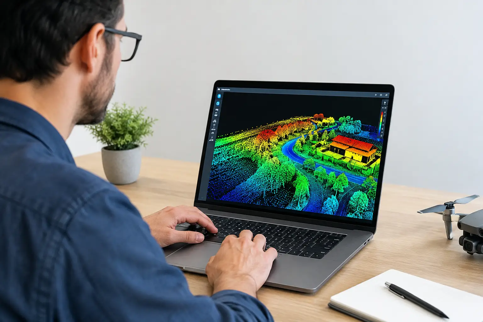
UAV LiDAR is particularly effective for embankment slopes, crest geometry, rock faces, spillway approaches, and terrain partially obscured by vegetation. It produces a dense point cloud that can be classified into ground, structure, and vegetation returns, then converted into digital terrain models, profiles, cross sections, and elevation-change surfaces.
LiDAR is valuable where subtle erosion gullies, crest settlement, slope bulging, or deformation around appurtenant structures must be measured consistently. Its performance depends on flight altitude, scan angle, point density, GNSS/IMU trajectory quality, control, and registration between survey epochs. Point clouds from different dates should not be compared until alignment quality is tested over known stable surfaces.
Photogrammetry for High-Resolution Surface Change
Drone photogrammetry provides detailed orthomosaics and dense surface models from overlapping imagery. It is well suited to documenting cracking, joint condition, riprap displacement, sinkholes, erosion, exposed seepage paths, and visible deterioration of concrete surfaces.
Photogrammetry can achieve strong relative detail, but it is sensitive to lighting, water glare, repetitive textures, vegetation movement, and poorly controlled image geometry. For embankment dams, image-based outputs are often most useful when paired with LiDAR terrain data: LiDAR supplies reliable bare-earth geometry, while imagery provides visual evidence for interpretation.
InSAR and Fixed Instrumentation for Time-Series Context
Satellite InSAR can detect broad, gradual displacement over large areas and is useful for screening reservoir rims, abutments, access corridors, and regional ground movement. However, its line-of-sight measurement geometry, coherence limitations, and atmospheric effects mean it should be interpreted by specialists and cross-validated before operational decisions are made.
Traditional instruments remain essential where continuous or subsurface information is required. GNSS monuments, prisms, inclinometers, piezometers, settlement plates, joint meters, and seepage monitoring systems provide temporal continuity that periodic aerial surveys cannot replace. UAV surveys extend this network by identifying where movement is occurring between instruments and by covering areas that are unsafe or inefficient to inspect on foot.
Process Change, Not Just Individual Surveys
A single digital elevation model shows condition at one point in time. Deformation assessment requires a controlled comparison between epochs. The core analytical products are elevation-difference maps, point-cloud-to-point-cloud distance calculations, crest and slope profiles, and movement vectors where the data supports them.
Before differencing, confirm that datasets share the same coordinate system, vertical datum, survey control, and processing standard. Then register them using stable reference surfaces outside the expected deformation zone. The comparison must include an uncertainty budget. If the calculated change is smaller than the combined uncertainty of the two datasets, it may not be a real movement signal.
For example, a 20-millimeter apparent crest settlement should not be treated as confirmed deformation if the repeatability of the acquisition and registration workflow is 30 millimeters. Conversely, a coherent band of elevation loss extending across several independent profiles may be significant even when each individual point contains noise. Spatial pattern, persistence, and agreement with field observations are decisive.
Interpret Movement in an Engineering Context
The highest-value output is not a colored change map. It is an interpretation that distinguishes operational response from anomalous behavior. Reservoir drawdown may expose slope movement that was previously submerged. Extended heat can alter concrete geometry. Rainfall can temporarily affect embankment moisture and surface condition. Construction traffic can disturb crest elevations locally without indicating internal instability.
Interpretation should integrate reservoir level records, rainfall, temperature, piezometric data, seepage measurements, maintenance activity, and previous inspections. A localized depression at the crest may warrant immediate field verification if it aligns with increased seepage or elevated piezometric pressure. The same depression may have a different meaning if it occurs beside a recently reconstructed utility trench.
This is where multi-sensor data fusion has practical value. LiDAR may quantify settlement, photogrammetry may reveal associated cracking or surface erosion, and field instrumentation may indicate whether the movement corresponds to changing internal hydraulic conditions. Cross-validation reduces the risk of both missed warning signs and unnecessary escalation.
Set Survey Frequency by Risk and Rate of Change
There is no universal monitoring interval. A stable, mature dam with consistent instrument readings may require annual or seasonal UAV surveys. A dam undergoing first filling, raising works, reservoir drawdown, major repairs, unusual rainfall, seismic activity, or observed movement may require monthly, weekly, or event-driven campaigns.
The interval should be short enough to identify acceleration before it becomes a safety issue. It should also be proportionate to the expected movement rate and the precision of the measurement method. Frequent surveys with weak control produce noise. Less frequent surveys with rigorous calibration may produce more useful trend evidence.
Deliver Results for Decisions, Not Visualization
A decision-grade deformation package should contain the acquisition plan, control report, QA/QC results, point clouds or surface models, orthomosaics where applicable, change-detection outputs, profiles through critical sections, anomaly register, and engineering interpretation. Each anomaly should identify its location, magnitude, confidence level, likely mechanism, supporting evidence, and recommended follow-up action.
Air Solutions applies this discipline through calibrated UAV LiDAR and photogrammetry workflows designed for traceable comparison in demanding infrastructure environments. The operational advantage is rapid mobilization without compromising the documentation required for technical governance.
The most useful next step is often not another broad inspection. It is a targeted repeat survey of the specific zone where geometry, instrumentation, and operating conditions indicate that the dam’s behavior may be changing.