A terrain model can look precise and still be wrong where the project matters most: beneath vegetation, along a haul-road edge, at a drainage crossing, or beside energized infrastructure. LiDAR vs photogrammetry accuracy is therefore not a simple sensor comparison. It is a question of what surface must be measured, what error tolerance the engineering decision allows, and whether the entire acquisition-to-deliverable workflow is calibrated and traceable.
For mining, utilities, water resources, and major construction programs, the correct choice is rarely driven by headline point density or camera resolution alone. Decision-grade mapping requires an error budget that accounts for sensor geometry, trajectory accuracy, survey control, environmental conditions, processing methods, and independent validation.
LiDAR vs Photogrammetry Accuracy: The Core Difference
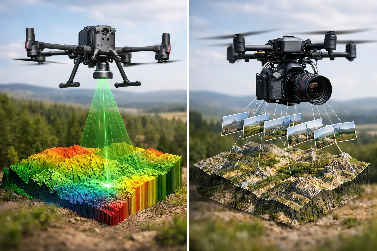
LiDAR measures distance directly. A laser scanner emits pulses and records the return time, generating three-dimensional points with each pulse. Airborne LiDAR can capture multiple returns from a single pulse, which is critical where vegetation creates gaps between the aircraft and the ground. Those returns can be classified to develop a bare-earth digital terrain model, provided the acquisition density and classification workflow are suitable for the site.
Photogrammetry derives three-dimensional geometry from overlapping images. Software identifies common features across photographs, calculates camera positions, and reconstructs a dense point cloud and surface model. The method is highly effective over visible, textured surfaces such as exposed rock, stockpiles, pavement, building facades, and construction earthworks.
The distinction matters because photogrammetry generally measures the topmost visible surface. It cannot reliably reconstruct terrain hidden by dense grass, shrubs, tree canopy, standing water, shadow, or low-texture materials. LiDAR is not immune to obstruction, but laser pulses have a greater probability of reaching the ground through partial canopy. In vegetated terrain, that physical advantage often determines whether the final model is suitable for drainage analysis, route design, flood modeling, or resource planning.
Neither sensor is inherently "more accurate" in every setting. A well-controlled photogrammetry mission over bare ground may produce excellent horizontal detail and vertical accuracy. A poorly planned LiDAR survey with weak trajectory data, inadequate overlap, or incorrect boresight calibration can produce a clean-looking point cloud with systematic offsets. Accuracy follows process control.
Accuracy Is More Than Point Density
Point density describes how many observations cover an area. It does not establish whether those observations are positioned correctly. Likewise, image ground sampling distance is not a guarantee of survey accuracy. A 2-centimeter pixel may support a highly detailed orthomosaic, but the final positional accuracy depends on camera calibration, image geometry, ground control, GNSS and inertial performance, and block adjustment quality.
For both methods, technical teams should separate three measures:
Absolute accuracy is the agreement between the mapped position and its true ground position in the project coordinate system. This is the measure that matters when data must tie into design control, asset records, cadastral references, or repeated monitoring surveys.
Relative accuracy is the consistency of measurements within the dataset. It affects volume calculations, local grade checks, structural deformation assessments, and feature-to-feature distances. A dataset can be internally consistent while still carrying a global horizontal or vertical shift.
Surface fidelity is how well the model represents the physical surface required by the application. This is where LiDAR and photogrammetry differ most. A photogrammetric surface may be accurate for the canopy, roof, or stockpile skin that it sees, while being unsuitable as a bare-earth terrain model beneath vegetation.
A procurement specification that asks only for "high accuracy" leaves material risk unresolved. It should define the required coordinate reference system, vertical datum, target surface type, spatial resolution, confidence level, and independent checkpoint acceptance criteria.
Where LiDAR Produces the More Defensible Result
LiDAR is normally the preferred method when the project requires terrain intelligence below partial vegetation cover or when surface texture is inconsistent. Common examples include wadi mapping, corridor surveys, drainage catchments, pipeline routes, utility corridors, mine expansion areas, and environmental baseline studies.
In these environments, a LiDAR point cloud can support ground classification and generate a digital terrain model that is less biased by vegetation than an image-derived surface. The benefit is operationally significant: a small elevation error in a drainage channel or crossing can affect flood routing, cut-and-fill estimates, and infrastructure design decisions.
LiDAR also provides direct three-dimensional observations without depending on visual texture. Uniform sand, dark surfaces, repetitive patterns, and shadowed areas can weaken photogrammetric matching. Desert projects may appear ideal for image mapping, but low-contrast terrain and feature-poor surfaces can still reduce the reliability of image-based reconstruction. LiDAR retains its ranging capability where image tie points are sparse.
That said, LiDAR accuracy is governed by disciplined calibration. Scanner range accuracy, scan angle, flight altitude, pulse repetition rate, GNSS base station or network corrections, inertial measurement unit performance, and boresight alignment all contribute to the result. Strip-to-strip alignment analysis is essential. If overlapping flight lines do not agree within the project tolerance, the point cloud should not proceed directly to classification or engineering extraction.
Where Photogrammetry Can Equal or Exceed LiDAR Detail
Over unobstructed, well-textured ground, photogrammetry can produce highly detailed surfaces and orthomosaics at an efficient cost per square kilometer. It is often the appropriate choice for quarry faces, stockpile volumetrics, construction progress, roof inspection, pavement condition context, and visible asset mapping.
Photogrammetry also delivers a major advantage that LiDAR alone does not: natural color imagery. For project teams, an orthomosaic makes it easier to identify materials, boundaries, erosion features, equipment, access routes, and site conditions. That visual context can improve interpretation and reporting when paired with accurate spatial data.
However, image acquisition geometry must be designed for the deliverable. Nadir-only imagery is often sufficient for orthomosaics and terrain over open ground, while oblique imagery may be necessary for facades, highwalls, structures, and complex industrial assets. Motion blur, rolling-shutter distortion, poor exposure, inadequate forward or side overlap, and changing illumination can degrade the reconstruction before processing begins.
Photogrammetry is also sensitive to surface movement. Wind-driven vegetation, moving machinery, water, dust, and reflective materials create artifacts or gaps. A survey team should treat these not as post-processing inconveniences, but as acquisition risks to be managed in the flight plan and site-access window.
Survey Control Determines Whether Accuracy Is Auditable
Direct georeferencing with RTK or PPK-equipped aircraft can reduce field control requirements and accelerate mobilization. It does not remove the need for verification. For both LiDAR and photogrammetry, independently surveyed checkpoints remain the strongest evidence that the delivered model meets the stated tolerance.
Ground control points constrain an image block and can improve photogrammetric reliability, particularly on large sites, steep terrain, or projects with demanding vertical specifications. Their distribution matters as much as their quantity. Control concentrated near a site entrance may produce acceptable results locally and undetected distortion at the perimeter.
For LiDAR, control supports trajectory validation, strip adjustment assessment, and final accuracy testing. Checkpoints should be placed on stable, clearly defined surfaces and kept separate from any points used to calibrate or adjust the dataset. This separation is what makes the result independently auditable rather than self-confirming.
The final report should document coordinate reference systems, datum transformations, control survey methods, sensor settings, flight parameters, calibration records, overlap analysis, classification logic, and checkpoint residuals. A technically defensible deliverable allows an owner, engineer, or regulator to understand not just the reported accuracy, but how it was achieved.
Selecting the Right Method for the Decision
The decision should begin with the required surface. If the task is to map visible construction progress or calculate stockpile volumes on exposed material, photogrammetry may provide the best combination of detail, visual context, and cost efficiency. If the task requires a reliable bare-earth model under vegetation, or must perform consistently across low-texture terrain, LiDAR is typically the lower-risk option.
In many industrial programs, the strongest solution is multi-sensor acquisition. LiDAR establishes the geometry and bare-earth terrain model. Calibrated imagery supplies visual interpretation, feature attribution, and stakeholder-ready mapping. Fusing both datasets can reduce ambiguity in asset inventories, geological interpretation, corridor planning, and environmental assessment.
Air Solutions applies this selection logic at the project-design stage rather than treating sensor choice as a standard package. The survey specification is built around the decision it must support, the conditions on site, and the QA/QC evidence needed for acceptance.
A lower acquisition cost is not a saving if the dataset cannot support design, permitting, or investment decisions without rework. Specify the surface, define the tolerance, require independent validation, and select the sensing method that remains reliable under the actual conditions of the project site.