A linear survey fails long before the aircraft launches if the corridor is treated as a narrow area map rather than an engineering decision system. A disciplined drone corridor mapping workflow converts a proposed or existing route into traceable terrain, asset, clearance, and constraint intelligence that design teams can use with confidence. For pipelines, transmission lines, roads, rail alignments, utility corridors, and water infrastructure, the objective is not simply dense point-cloud coverage. It is a controlled dataset with defined accuracy, complete spatial continuity, documented QA/QC, and clear acceptance criteria.
Start with the decision, not the flight plan
Corridor mapping should begin with the decisions the client needs to make. A route-selection study, a detailed design survey, a construction progress assessment, and an asset-integrity inspection may all cover the same alignment, but they require different sensors, tolerances, classifications, and reporting outputs.
The project team should establish the corridor centerline, required width, chainage convention, coordinate reference system, vertical datum, and required deliverables before planning acquisition. This prevents a common failure mode: collecting imagery or LiDAR that appears technically sound but cannot be integrated with engineering design files, land records, or existing GIS layers.
Accuracy requirements must be stated in measurable terms. Horizontal and vertical tolerances, point density, image ground sampling distance, vegetation penetration requirements, breakline needs, and feature attribution standards should be agreed at the outset. A 3D corridor model for early feasibility can tolerate different uncertainty than a survey supporting grading quantities, drainage design, or clearance verification.
Define the operating envelope
Long, narrow projects create operational constraints that are not present in a compact site survey. Terrain can change rapidly along the route. Communications coverage may be inconsistent. Land access, aviation restrictions, active works, and third-party assets can interrupt the planned mission. The acquisition strategy must account for these conditions rather than assuming every flight block will perform identically.
Desktop preparation combines current satellite imagery, digital elevation models, known utility records, alignment drawings, airspace constraints, and project-specific hazards. The team then divides the corridor into operationally practical blocks, with overlap between blocks sufficient to maintain data continuity and support later reconciliation.
In desert and high-temperature environments, mission design must also account for thermal loading, battery performance, surface reflectance, dust, wind, and GNSS conditions. These factors affect both flight endurance and data quality. A shorter, repeatable mission block with planned control checks is often more defensible than an ambitious sortie that produces uneven coverage or forces rushed field decisions.
Select sensors against the asset risk
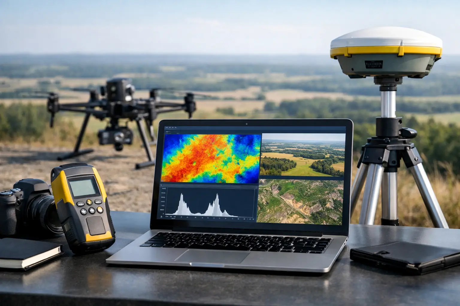
Photogrammetry is effective where high-resolution orthomosaics, textured 3D surfaces, visible asset condition, stockpile measurements, and surface feature extraction are required. It depends on adequate image overlap, stable illumination, and visible ground texture. Dense vegetation, low-contrast terrain, or complex wire environments can limit its reliability as a sole source of terrain data.
LiDAR is typically the preferred modality when the corridor includes vegetation, steep terrain, engineered embankments, dense structures, or clearance-critical assets. Properly calibrated LiDAR supports bare-earth classification, cross sections, powerline modeling, drainage analysis, and precise surface extraction. The required point density depends on the target features, flight altitude, speed, scanner configuration, and expected classification outcome.
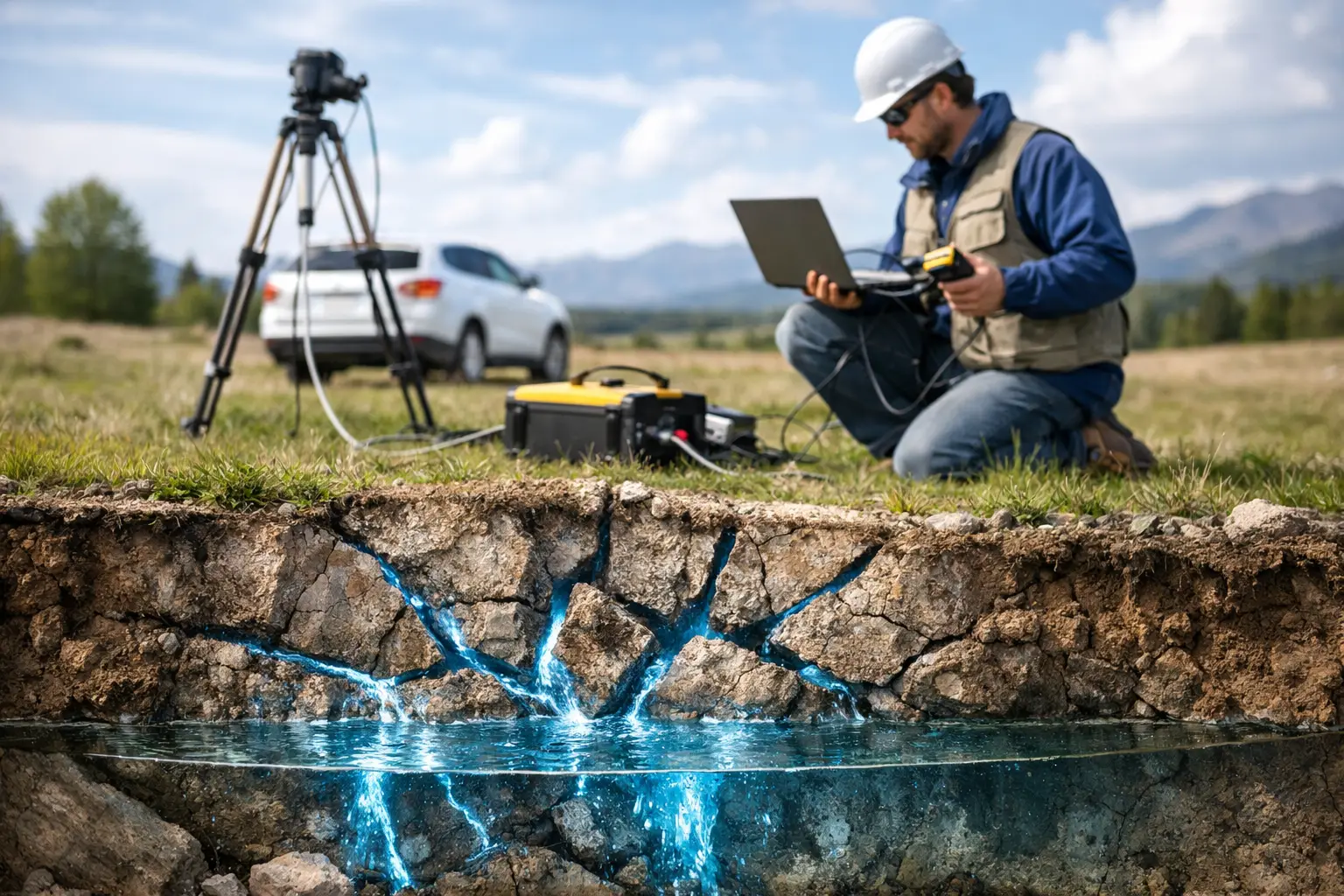
Magnetic, electromagnetic, radiometric, hyperspectral, or GPR data may be added where the corridor decision extends below the surface or beyond geometry. Examples include utility risk screening, geologic structure mapping, groundwater investigations, contamination indicators, and mineralized zone characterization. Multi-sensor acquisition should be specified only when it answers a defined engineering, environmental, or exploration question. More data is not inherently better if it creates processing complexity without improving the decision.
Build survey control and calibration into the workflow
A defensible corridor survey requires a coherent geodetic framework. Ground control points, check points, base-station data, network RTK corrections, or PPK processing may each have a role, depending on the required accuracy and site conditions. The essential requirement is that control is independent enough to test the final product, not merely help generate it.
Control distribution matters. A few points clustered near a mobilization area cannot validate a corridor extending for tens of miles across varying terrain. Check points should be distributed across the project length and across representative surface conditions, including cuts, fills, hard ground, vegetated areas, and complex infrastructure where applicable.
Sensor calibration is equally critical. LiDAR boresight alignment, IMU performance, camera calibration, timing synchronization, and GNSS trajectory quality all influence final accuracy. For multi-flight corridors, adjacent swaths and mission blocks should be compared for elevation bias, planimetric displacement, point-density variation, and coverage gaps. These checks form part of the audit trail, not an optional processing exercise.
Execute acquisition with live quality control
Field execution should operate against a written mission plan, but it must remain responsive to actual conditions. Before each launch, teams verify airspace status, weather, equipment condition, payload settings, control availability, communications, emergency procedures, and local worksite hazards. During acquisition, operators monitor positional solution quality, sensor health, image exposure where relevant, flight-path conformance, overlap, and coverage boundaries.
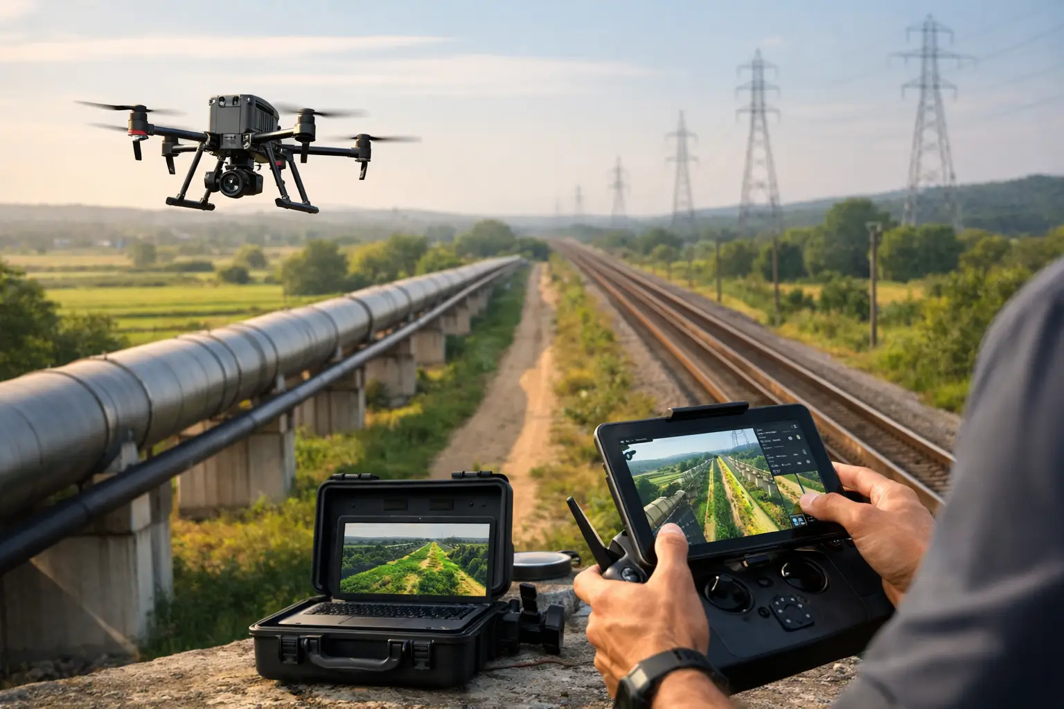
For corridor work, terrain-following parameters deserve particular attention. An aircraft holding a fixed altitude above its launch point can produce inconsistent ground resolution and point density over changing relief. Terrain-aware planning improves consistency, although it requires reliable terrain inputs and suitable obstacle margins. Where powerlines, towers, cranes, or other vertical assets are present, the plan must include conservative separation and asset-specific capture geometry.
A disciplined field team does not wait until final processing to discover a coverage issue. End-of-flight review should identify gaps, poor trajectory segments, excessive motion, weak overlap, or sensor anomalies while the aircraft and crew remain mobilized. Targeted reflight at this stage is faster and less expensive than remobilization.
Process the corridor as an engineered dataset
The processing chain begins with secure data ingest, file verification, and preservation of raw records. Flight logs, GNSS observations, calibration files, sensor configuration records, control observations, and field notes should remain associated with each acquisition block. This provides traceability from a final contour, cross section, or anomaly interpretation back to the source data.
LiDAR processing typically includes trajectory optimization, strip alignment, point-cloud generation, noise removal, classification, and accuracy assessment against independent checkpoints. Photogrammetry processing includes image quality screening, aerial triangulation, dense reconstruction, orthomosaic generation, and surface-model production. Both methods require careful edge matching between blocks so that the corridor functions as one continuous survey, not a collection of visually similar tiles.
Derived products should reflect the client’s engineering use case. Depending on the assignment, outputs may include classified point clouds, digital terrain models, digital surface models, contours, planimetric feature layers, centerline profiles, cross sections, cut-and-fill surfaces, obstruction inventories, clearance models, orthomosaics, and GIS-ready datasets. For utility and subsurface investigations, interpreted target layers and confidence classifications may be more valuable than raw geophysical grids alone.
Apply QA/QC that can survive technical review
QA/QC should be reported quantitatively. Accuracy statistics need to distinguish between ground-control residuals and independent checkpoint results. Coverage reports should identify any excluded areas. Point-density maps, strip-difference analysis, classification review, and coordinate-system verification should be included where relevant.
A useful acceptance package also documents limitations. Water surfaces, deep shadow, dense canopy, highly reflective materials, active machinery, and restricted access can affect capture or interpretation. Stating these conditions clearly is not a weakness. It allows engineers and project owners to understand where supplementary field survey, design assumptions, or follow-up inspection may be required.
Deliver intelligence that fits project systems
The final stage of a drone corridor mapping workflow is integration. Files must be structured for use in CAD, GIS, BIM, asset-management, and environmental reporting environments. Naming conventions, chainage references, layer schemas, metadata, coordinate definitions, and version controls should be specified so the data can be consumed without repeated clarification.
For major infrastructure programs, the strongest deliverable is not the largest file package. It is a decision-grade package that shows what was measured, how it was validated, where uncertainty remains, and how the findings affect route, design, construction, or maintenance actions. Air Solutions applies this discipline across airborne sensing programs where speed of mobilization must be matched by technical accountability.
A well-executed corridor survey gives project teams a common spatial record before conditions change again. That record becomes more valuable when it is designed from the first day to support the next engineering decision, rather than merely document the last flight.