A productive water well is rarely found by locating a single obvious crack in the ground. In fractured bedrock, groundwater occurs where faults, joints, shear zones, weathered zones, and fracture intersections create connected pathways with sufficient aperture, storage, and recharge. Knowing how to detect groundwater fractures therefore requires more than one sensor or a favorable surface feature. It requires a calibrated investigation that converts geological evidence into a drillable, defensible target.
For project owners, the objective is not simply to map lineaments. It is to reduce uncertainty before mobilizing a drilling rig, particularly where failed boreholes carry material cost, schedule, and operational consequences. The strongest programs combine terrain intelligence, geophysics, field verification, and drilling feedback in a traceable interpretation workflow.
Groundwater Fractures Are Not All Productive
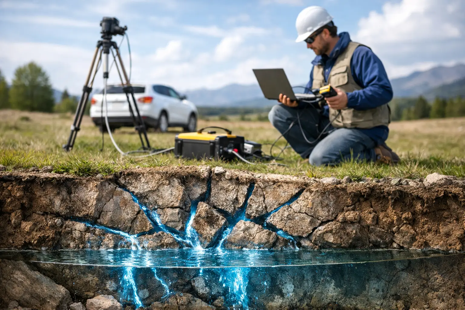
A fracture can be structurally real and still have little groundwater value. Some fractures are mineralized, sealed by clay or secondary minerals, isolated from recharge, or too narrow to sustain the required yield. Others may transmit water efficiently but provide limited storage. Conversely, a broad weathered bedrock zone can produce more reliably than a visually prominent fault.
The critical question is whether a structural feature is hydraulically connected. Productive targets typically show a combination of fracture density, favorable orientation, continuity at depth, weathering or alteration, topographic position, and a plausible recharge mechanism. In arid settings, this assessment must also account for ephemeral drainage, alluvial cover, salinity risk, and the distinction between shallow perched water and a sustainable bedrock aquifer.
Surface observations alone cannot establish those conditions. They provide hypotheses that geophysical data and drilling must test.
How to Detect Groundwater Fractures in a Controlled Workflow
Start With Geological and Terrain Constraints
The first stage is a desktop and reconnaissance review of regional geology, existing borehole records, hydrogeological reports, topographic data, drainage networks, and satellite imagery. This establishes the dominant rock types, known fault systems, expected depth to bedrock, and likely recharge corridors.
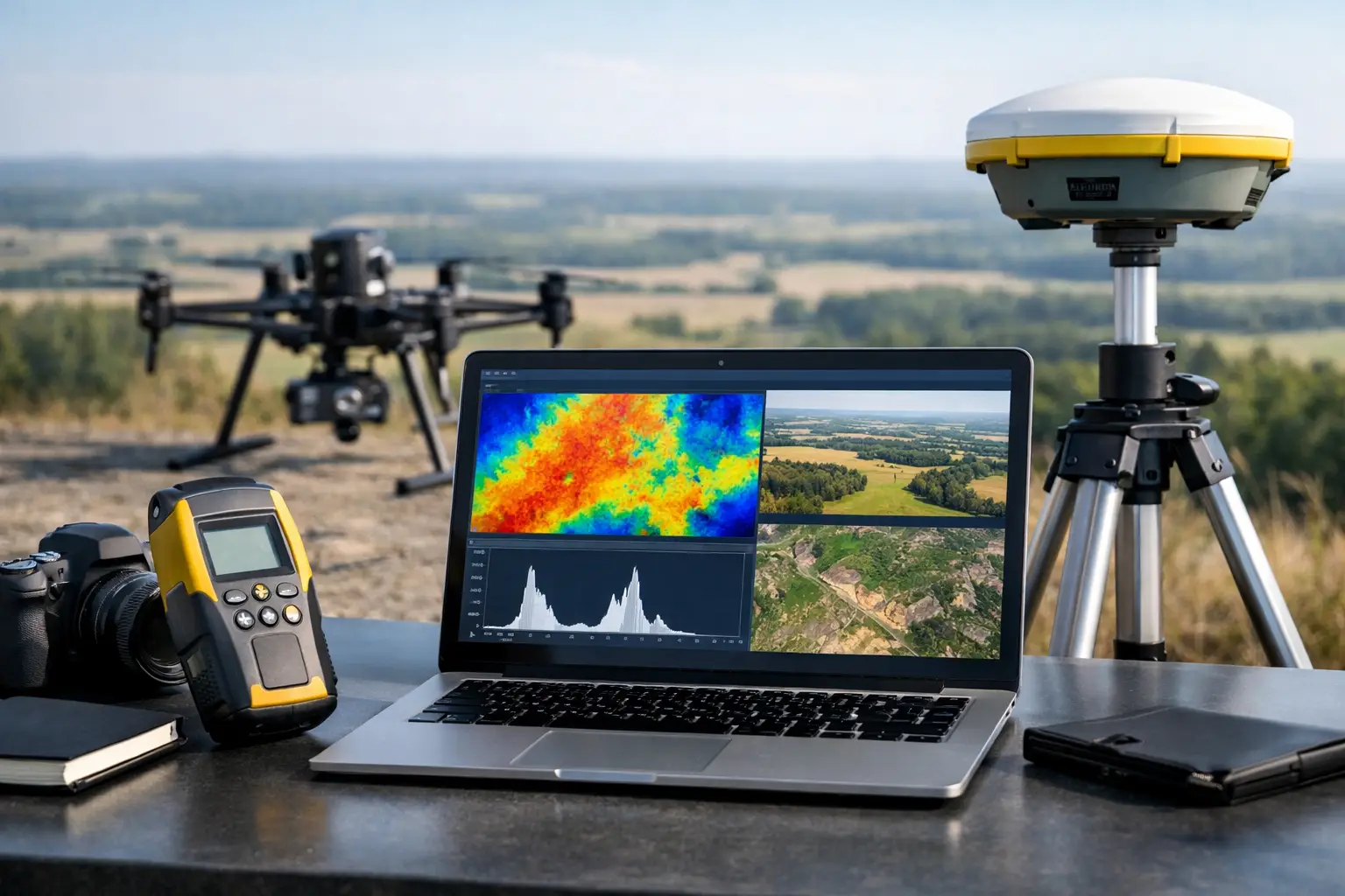
High-resolution terrain mapping is particularly valuable because fractures often influence drainage alignment, slope breaks, vegetation patterns, escarpments, and subtle linear depressions. LiDAR and drone photogrammetry can reveal these features at a scale that conventional regional mapping may miss, including lineaments hidden by sparse terrain expression or complex access conditions.
A lineament map is not a groundwater map. Its role is to identify structural candidates, rank them by geometry and setting, and guide where subsurface measurements should be collected. Intersections between major fracture sets, contacts between contrasting rock units, and structurally controlled valleys commonly warrant closer investigation, but each must be tested against local geology.
Use Geophysics to Map Subsurface Contrast
Electrical and electromagnetic methods are central to fractured-groundwater exploration because water-filled fractures, clay-rich weathered zones, and saturated materials may exhibit lower electrical resistivity than intact, dry bedrock. Electrical resistivity tomography can image lateral and vertical resistivity variation along targeted profiles, helping define potentially weathered or fractured zones beneath the surface.
This result requires careful interpretation. Low resistivity does not automatically mean fresh groundwater. It can also indicate clay, saline water, conductive minerals, or saturated alluvium. High resistivity is likewise not proof of dry rock, as open fractures within competent bedrock may be below the resolution of the survey or have only modest contrast with the host formation.
Electromagnetic surveys can rapidly extend coverage over larger areas and identify conductivity patterns associated with weathering, faults, and groundwater-bearing structures. Airborne or drone-based electromagnetic acquisition is especially useful where ground access is slow, hazardous, or disruptive to active operations. It can provide systematic coverage and support rapid targeting across broad corridors before follow-up ground geophysics.
Magnetic surveys add a different form of evidence. Faulting, alteration, weathering, and lithological contacts can disrupt the magnetic signature of bedrock. Aeromagnetic or drone magnetic data may therefore delineate structural trends that are poorly expressed at the surface. Magnetic data do not detect water directly, but they can materially improve structural interpretation when fused with electrical, terrain, and geological datasets.
The operating principle is complementary evidence. A lineament that aligns with a magnetic break, a conductive or moderately resistive anomaly, a drainage feature, and mapped fracture orientation deserves a higher target ranking than an anomaly identified by one dataset alone.
Design Profiles Around the Geological Model
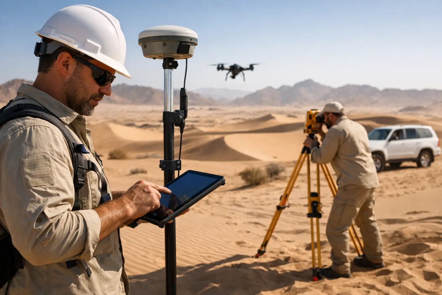
Survey geometry should be driven by the expected fracture orientation, not by convenient straight lines alone. Profiles commonly cross the anticipated fault or fracture trend at a high angle, improving the ability to resolve the width, dip, and continuity of the target zone. Where fracture systems are complex, intersecting profiles or a compact grid can distinguish a localized anomaly from a regionally continuous feature.
Acquisition settings matter. Electrode spacing, line length, sensor altitude, sampling density, terrain correction, and cultural-noise controls determine what depth and feature scale can be resolved. A survey designed only for shallow anomalies may miss the deeper structural zone that controls yield. A survey designed for excessive depth may lose the near-surface resolution needed to separate weathered overburden from fractured bedrock.
This is where disciplined QA/QC becomes decisive. Positioning, calibration, repeat lines, noise assessment, processing parameters, and inversion assumptions should be documented. A technically attractive image without acquisition traceability is difficult to defend in an investment, permitting, or engineering review.
Validate the Interpretation Before Committing to Production
Geophysics identifies probability, not certainty. Ground validation should examine outcrops, fracture infill, fault gouge, spring locations, drainage behavior, and accessible structural exposures. If existing wells are available, their construction details, water strikes, static water levels, pumping performance, and water-quality records should be incorporated into the model.
Exploratory drilling is the decisive test. Drill logs should record lithology, weathering profile, fracture frequency, water inflows, drilling losses, and casing intervals with consistent depth control. Borehole imaging, caliper logging, and flow logging can further identify open fractures and determine which intervals contribute water under static and pumping conditions.
A water strike during drilling should not be treated as a final success criterion. Step-drawdown and constant-rate pumping tests establish yield, drawdown behavior, transmissivity, recovery, and longer-term sustainability. Water chemistry is equally relevant, particularly in coastal, evaporitic, or industrial environments where conductive groundwater may be saline or otherwise unsuitable for the intended use.
Select Methods According to Site Conditions
There is no universal sensor stack for detecting groundwater fractures. In hard, exposed bedrock, structural mapping, magnetics, and targeted resistivity profiles may provide an efficient basis for drilling. In areas with thick conductive clays, salinity, or alluvial cover, resistivity interpretation becomes less direct and may require electromagnetic coverage, borehole control, or additional geological constraints.
Topography also changes the approach. Steep terrain can distort electrical measurements and limit ground deployment, while drone-based magnetic, photogrammetric, and LiDAR acquisition can establish a safer and more complete structural framework. On large infrastructure or mining sites, survey planning must also account for powerlines, fences, pipelines, buried utilities, active plant, and access restrictions that can affect sensor performance.
The appropriate method depends on the decision being made. A reconnaissance program intended to prioritize several drilling areas does not need the same density or cost profile as a final well-siting investigation. Defining that decision threshold at the outset prevents both under-surveying and unnecessary data collection.
Specify Decision-Grade Deliverables
A useful groundwater-fracture investigation should deliver more than imagery, anomaly maps, or raw sensor files. Decision-makers need an interpreted geological model that identifies candidate fracture corridors, explains the evidence supporting each target, states the limitations, and ranks drilling locations by probability and consequence.
The final package should include survey coverage, acquisition specifications, calibration and QA/QC records, processed datasets, interpreted profiles or sections, lineament and structural maps, target coordinates, and a clear drilling rationale. Cross-validation between sensing modalities should be explicit. This makes the result auditable by hydrologists, geologists, engineering teams, and technical procurement reviewers.
Air Solutions applies this integrated approach through drone-based terrain, magnetic, electromagnetic, and imaging capability, producing interpreted geospatial intelligence rather than leaving clients to reconcile disconnected sensor outputs.
The most reliable groundwater target is not the strongest single anomaly. It is the location where geology, terrain, geophysics, and borehole evidence converge - and where the remaining uncertainty is understood before capital is committed to drilling.