A utility strike is rarely caused by a single failure. More often, it begins with incomplete records, an unverified field mark, a coordinate mismatch, or an assumption that one detection method has resolved every buried asset. Knowing how to map subsurface utilities means building a controlled evidence chain that converts uncertain underground conditions into design-grade, excavation-ready intelligence.
For infrastructure owners, EPC teams, and public agencies, the objective is not simply to produce a drawing with colored lines. It is to identify what is present, establish its horizontal and vertical position to a known confidence level, record the method used to determine that position, and communicate remaining uncertainty before construction mobilizes.
Start With the Decision, Not the Sensor
Utility mapping should be scoped against the decision it must support. A route-selection study, preliminary design package, trenchless crossing, plant expansion, and active excavation permit each require different confidence levels. Treating them as identical creates either unnecessary field cost or unacceptable residual risk.
Define the survey boundary, anticipated excavation depths, required positional tolerances, coordinate reference system, deliverable format, and acceptance criteria before fieldwork begins. The scope should also identify critical assets: high-pressure gas, electrical transmission, process lines, fiber-optic corridors, drainage networks, and legacy facilities with poor documentation.
In the United States, ASCE 38-22 provides a useful framework for communicating utility quality levels. Quality Level D is based on existing records and owner recollection. Quality Level C correlates visible surface evidence with record information. Quality Level B uses surface geophysics to designate probable horizontal locations. Quality Level A verifies location and depth through nondestructive exposure, commonly vacuum excavation. The standard is not a substitute for engineering judgment, but it provides a disciplined way to separate observed facts from interpreted positions.
Build a Controlled Records Baseline
The first field activity is often desk-based. Collect utility owner records, as-built drawings, GIS exports, prior survey files, permits, site plans, aerial imagery, and construction photographs where available. These documents establish hypotheses, not ground truth.
Each source should be cataloged by date, origin, coordinate system, stated accuracy, and relevance to the work area. Older facilities may have been installed from paper plans, transformed between coordinate systems, or modified without complete as-builts. A line that appears precise on a CAD drawing may carry no verified positional accuracy.
Field teams should then inspect visible evidence: manholes, valve boxes, hydrants, meters, utility poles, cabinets, markers, drainage inlets, and building service entries. Survey these features on a verified control network. This converts surface observations into spatial constraints that can be tested against records and geophysical responses.
How to Map Subsurface Utilities With Complementary Methods
No single instrument detects every utility in every ground condition. Effective mapping combines methods according to utility material, expected depth, soil conductivity, site access, congestion, and the consequences of error.
Electromagnetic locating is highly effective for conductive utilities that can be directly connected, clamped, or energized through an induced signal. It can trace metallic pipes, power cables, and tracer wires with speed, but results can be distorted by signal bleed, parallel lines, congested corridors, poor grounding, and discontinuous conductors. A detected signal indicates an electromagnetic response, not automatic confirmation of pipe identity or depth.
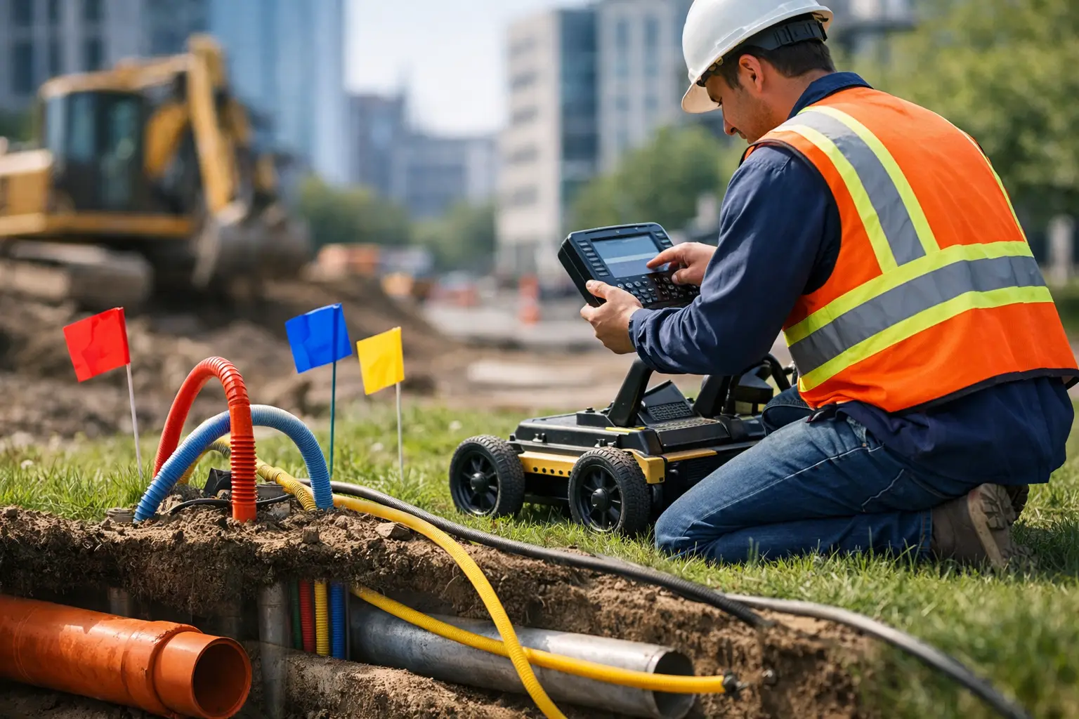
Ground-penetrating radar can identify both metallic and nonmetallic targets, including some plastic pipes, conduits, voids, and buried structures. Its performance depends heavily on soil conditions. Dry, resistive soils can support useful penetration and target definition, while conductive clays, saline ground, and reinforced slabs can significantly limit depth or produce complex reflections. GPR is most valuable when operators acquire gridded data, evaluate profiles in context, and distinguish probable utilities from geologic layering and construction debris.
Magnetic methods can help identify ferrous infrastructure such as cast-iron pipelines, steel casings, buried tanks, and magnetic debris. They are particularly useful as a complementary screening tool over larger areas, but they do not identify every metallic utility and can be affected by fences, vehicles, rebar, and surface clutter.
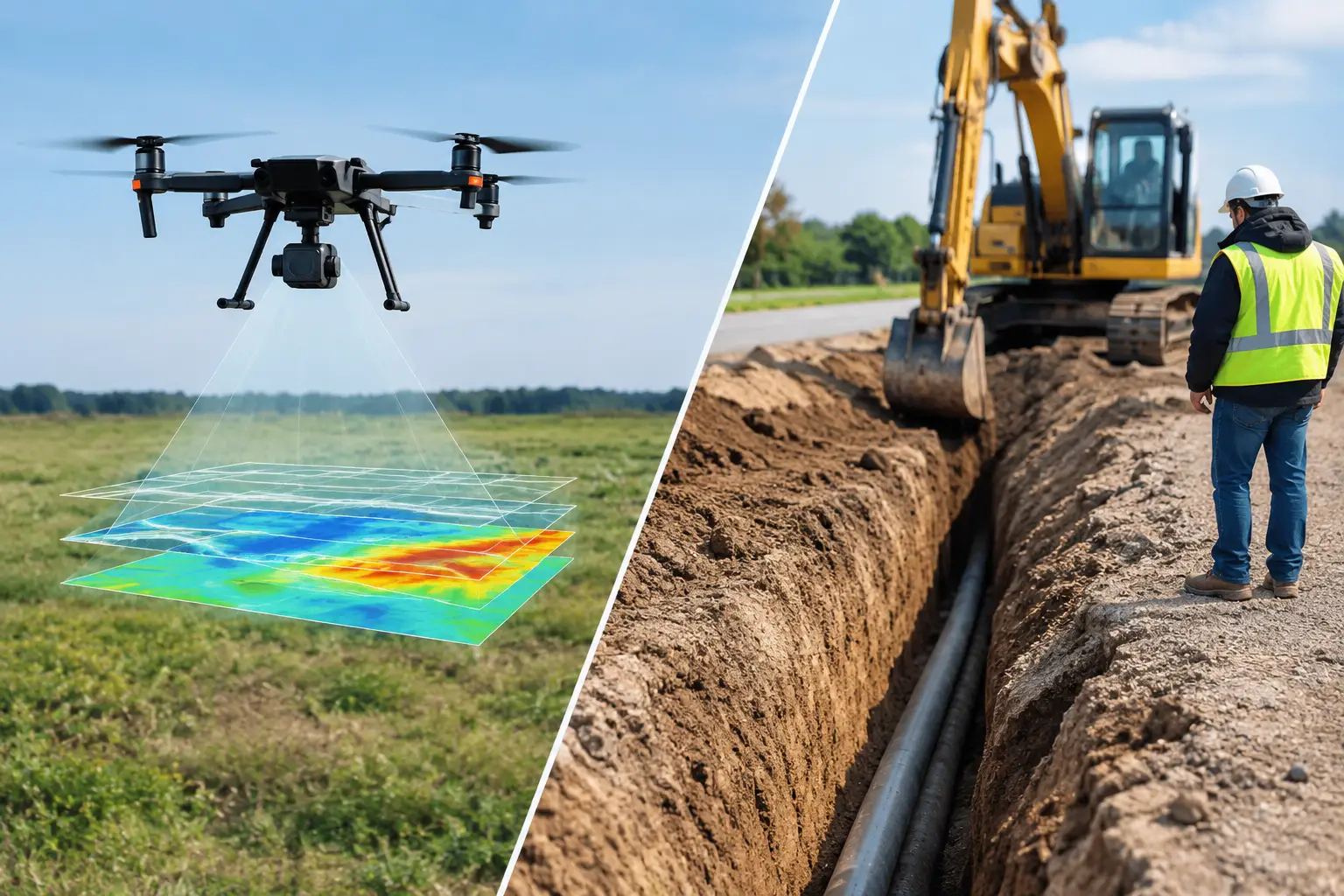
For broad sites, drone-derived photogrammetry or LiDAR can provide current terrain models, orthomosaics, and surveyed surface context. These datasets do not see through soil, but they strengthen utility intelligence by documenting access routes, drainage patterns, grade changes, exposed infrastructure, and the relationship between design features and field evidence. Airborne mapping is therefore a force multiplier for control, context, and corridor planning, not a replacement for subsurface geophysics or daylighting.
Establish Survey Control Before Designation
A technically capable detection program can still fail if its coordinates are unreliable. Establish project control tied to the required datum and vertical reference before utility positions are captured. Document instrument calibration, control checks, GNSS conditions where applicable, and any site constraints affecting accuracy.
Designated alignments should be surveyed as continuous features rather than isolated points where practical. Capture changes in direction, depth observations, crossings, appurtenances, and signal behavior. Record field notes that explain how each line was identified: direct connection, induction, passive sweep, GPR anomaly, record correlation, or physical verification.
This evidence matters when the map is reviewed months later by a designer, contractor, owner, or regulator. A line without a stated detection method can be mistaken for a verified asset when it is only an interpreted indication.
Cross-Validate Before You Assign Confidence
The strongest utility interpretations are supported by independent evidence. A conductive line traced from a valve box and correlated with a GPR hyperbola carries more confidence than a line inferred from a single passive electromagnetic sweep. Conversely, a conflict between methods is a finding, not an inconvenience to be edited away.
Cross-validation should test location, continuity, probable utility type, and depth. If records show a water main but electromagnetic tracing follows a nearby cable route, both possibilities must remain visible in the interpretation. If a GPR target diverges from a recorded alignment, investigate whether the discrepancy reflects an abandoned line, a construction deviation, or a non-utility target.
At high-risk crossings, congested plant areas, and proposed excavation zones, Quality Level A verification is often the controlling step. Vacuum excavation exposes the utility with limited disturbance, allowing direct measurement of material, diameter, depth, and position. It also reveals conditions surface methods cannot reliably resolve, including multiple stacked utilities, abandoned infrastructure, and undocumented encasements.
Produce an Auditable Utility Deliverable
A useful utility map is a managed technical record, not a visually attractive plan alone. The final package should distinguish verified, detected, inferred, and record-only features through clear symbology. Each utility should carry attributes for owner where known, utility type, material where confirmed, detection method, quality level, estimated depth, survey date, and confidence limitations.
For engineering use, deliver the information in the project coordinate system and in formats that support CAD, GIS, and construction workflows. Include a utility base map, control report, methodology statement, equipment and calibration records, field photographs, anomaly register, and a concise limitations section. Where depth is derived from electromagnetic or GPR interpretation, label it accordingly rather than presenting it as directly measured.
QA/QC should include independent review of linework topology, coordinate consistency, attribute completeness, control residuals, and conflicts between field observations and source records. A fully auditable deliverable makes it possible to trace each mapped feature back to its evidence and the conditions under which it was observed.
Manage the Residual Risk
Subsurface utility mapping reduces uncertainty; it does not eliminate it. Deep assets, nonconductive pipes without tracer wire, shielded cables, inaccessible corridors, conductive soils, dense reinforcement, and undocumented modifications can all constrain detection. The appropriate response is not to overstate certainty. It is to identify the limitation, define the remaining exposure, and recommend the next verification action.
Before excavation, translate the map into a field-ready control process. Mark designated lines, establish tolerance zones, brief operators on quality levels and conflicts, and require controlled exposure where the consequence of a strike is material. Update the utility model when daylighting reveals new information. A map should remain a living project record through construction, not a static preconstruction exhibit.
The best utility mapping programs make uncertainty visible early, when it can still be managed through design adjustment, targeted verification, and disciplined field controls. That is what turns subsurface intelligence into safer construction and more defensible project decisions.