A conductive anomaly is not automatically a water-bearing zone, a buried utility, or mineralization. It may be saline groundwater, clay-rich overburden, cultural interference, or a change in lithology. That distinction is why EM vs resistivity surveys should be treated as a survey-design decision, not a sensor-selection exercise. Both methods characterize electrical properties of the subsurface, but they respond to different physical mechanisms, operate at different speeds, and produce different levels of depth control.
For mining, groundwater, utility, and infrastructure programs, the correct choice depends on the decision the data must support. A fast reconnaissance campaign requires a different method than a borehole-siting investigation, trenchless crossing design, or detailed foundation assessment. The strongest programs frequently use both, with each dataset constrained by geological control, ground truth, and documented QA/QC.
The Core Difference Between EM and Resistivity
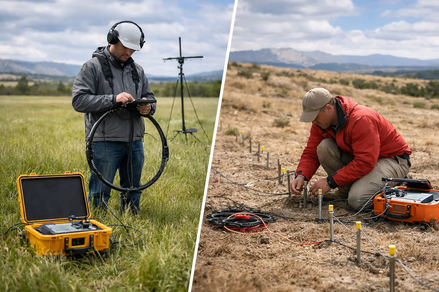
Electromagnetic, or EM, surveys induce a time-varying electromagnetic field and measure the ground's secondary response. That response is controlled primarily by electrical conductivity. Conductive materials, such as saline water, clays, graphite, sulfides, leachate, and some metallic infrastructure, can produce strong EM responses. Resistive materials, including dry sand, competent bedrock, fresh groundwater, and certain voids, tend to produce weaker responses.
Electrical resistivity tomography, commonly called ERT, injects a controlled electrical current into the ground through electrodes and measures resulting voltage differences at other electrodes. These measurements are inverted to estimate a two-dimensional or three-dimensional resistivity distribution. Resistivity is the inverse of conductivity, but the two methods are not interchangeable. ERT measures the response of a defined electrode array in direct contact with the ground, while EM measures induced fields without requiring electrodes.
The operational result is clear: EM can cover large areas rapidly with minimal ground disturbance, while resistivity generally delivers more explicit depth imaging and local structural definition where electrode deployment is practical.
EM vs Resistivity Surveys: Speed, Depth, and Resolution
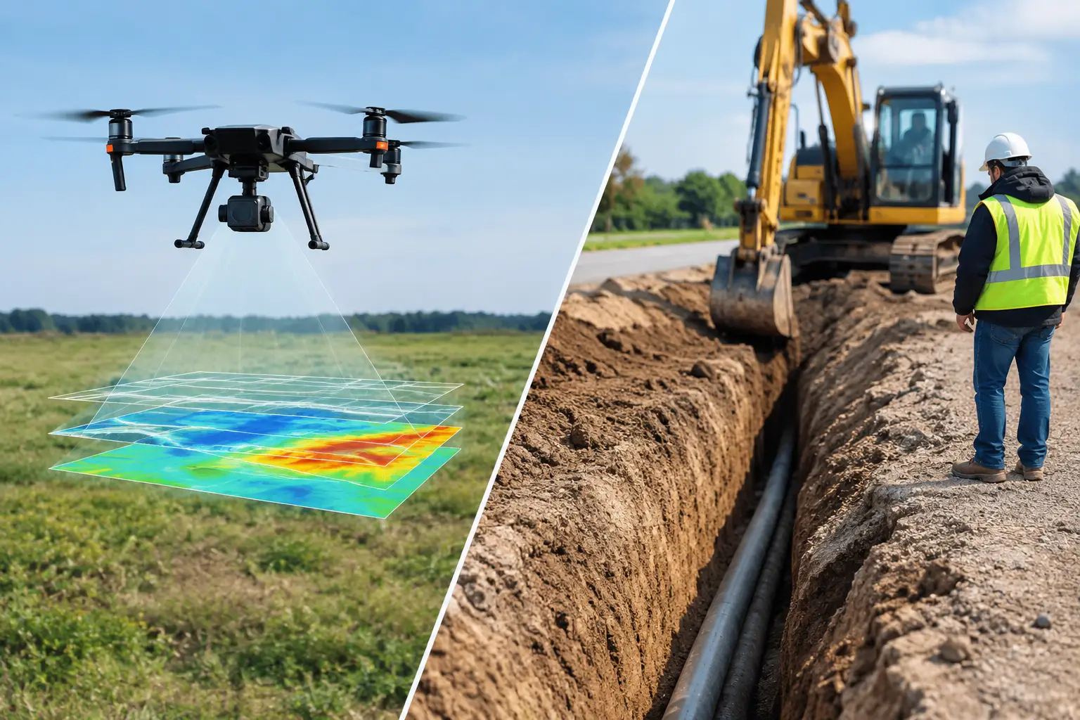
Survey speed is often the first differentiator. Ground EM can be deployed quickly along traverses, and airborne EM systems can collect regional-scale data over terrain that is difficult, hazardous, or expensive to access on foot. For large exploration licenses, corridor planning, or early groundwater screening, this coverage rate can materially shorten the time required to identify priority targets.
Resistivity acquisition is slower. Electrode positions must be laid out, coupled to the ground, checked for contact resistance, and sequenced through a predefined array. In desert environments, dry or rocky surface conditions may require wetting, conductive gel, drilled electrode points, or other controlled measures to achieve stable contact. These requirements add time, but they also provide a more controlled measurement geometry.
Depth of investigation depends on several variables, not a single manufacturer specification. For EM, depth is influenced by frequency, transmitter-receiver spacing, system moment, altitude, terrain clearance, and the conductivity of near-surface materials. Highly conductive shallow ground can mask deeper targets. A system may detect a deep conductor under favorable conditions, yet it may not resolve whether that conductor is a continuous layer, a narrow fracture zone, or a localized body without supporting information.
For ERT, depth depends mainly on electrode spacing, array geometry, line length, signal quality, and subsurface resistivity contrast. Larger spacing can investigate deeper, but resolution decreases as the survey expands. The deepest portions of an ERT section are also less constrained than shallow areas. A disciplined interpretation therefore reports sensitivity, inversion parameters, data misfit, and uncertainty rather than presenting every color boundary as a confirmed geological contact.
Where EM Produces the Strongest Value
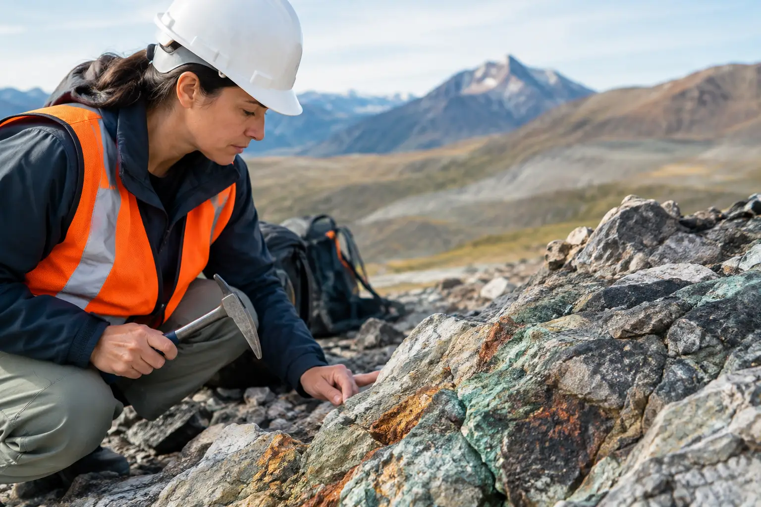
EM is well suited to rapid conductivity mapping and target generation. In mineral exploration, it can identify conductive trends associated with sulfides, graphite, alteration zones, paleochannels, or structurally controlled groundwater. In environmental and infrastructure work, it can help locate conductive plumes, map salinity variation, identify buried metallic features, and distinguish broad changes in overburden character.
Airborne and drone-enabled EM workflows are particularly valuable where access is constrained by heat, terrain, active operations, or safety controls. They reduce field exposure while providing consistent line spacing and traceable positioning across wide areas. However, airborne EM is not a replacement for every ground investigation. Flight altitude, cultural noise, powerline interference, and target size must be evaluated during planning. Small, shallow, or closely spaced utilities may require dedicated ground geophysics and direct verification.
EM should be selected when the program requires rapid coverage, when conductivity contrast is expected to be meaningful, and when the primary question is where to investigate next. It is especially effective as a calibrated reconnaissance tool before drilling, trenching, detailed ERT, or other follow-up work.
Where Resistivity Is the Better Tool
Resistivity is often the preferred method when a project needs a sectioned image of shallow-to-intermediate subsurface conditions along a specific alignment or site. Common applications include groundwater prospecting, aquifer geometry, weathered-bedrock mapping, seepage investigations, landfill characterization, foundation studies, cavity assessment, and route planning for pipelines or utilities.
Its principal advantage is interpretive structure. A properly designed ERT line can show lateral and vertical changes that are operationally useful for selecting borehole locations, assessing likely saturated zones, delineating bedrock relief, or identifying possible weak ground. In groundwater work, resistivity can help differentiate coarse alluvium, clay, saline water, and fresher saturated materials when combined with borehole logs and hydrochemical data.
The qualification matters. Low resistivity does not prove productive groundwater. Clay and saline water can both appear conductive, while fresh groundwater in a coarse aquifer may present as relatively resistive. Similarly, a high-resistivity zone may indicate dry competent rock, but it can also reflect a void, coarse dry fill, or near-surface contact limitations. Resistivity interpretation must remain tied to local geology and verified where the investment decision warrants it.
A Defensible Survey Design Starts With the Decision
The most common error is specifying a method before defining the target and decision threshold. A better approach begins with the required deliverable: regional target ranking, a drill-ready anomaly, a groundwater well location, an engineering corridor model, or a verified utility risk map. From there, the survey can be designed around target depth, expected contrast, required resolution, access constraints, and acceptable uncertainty.
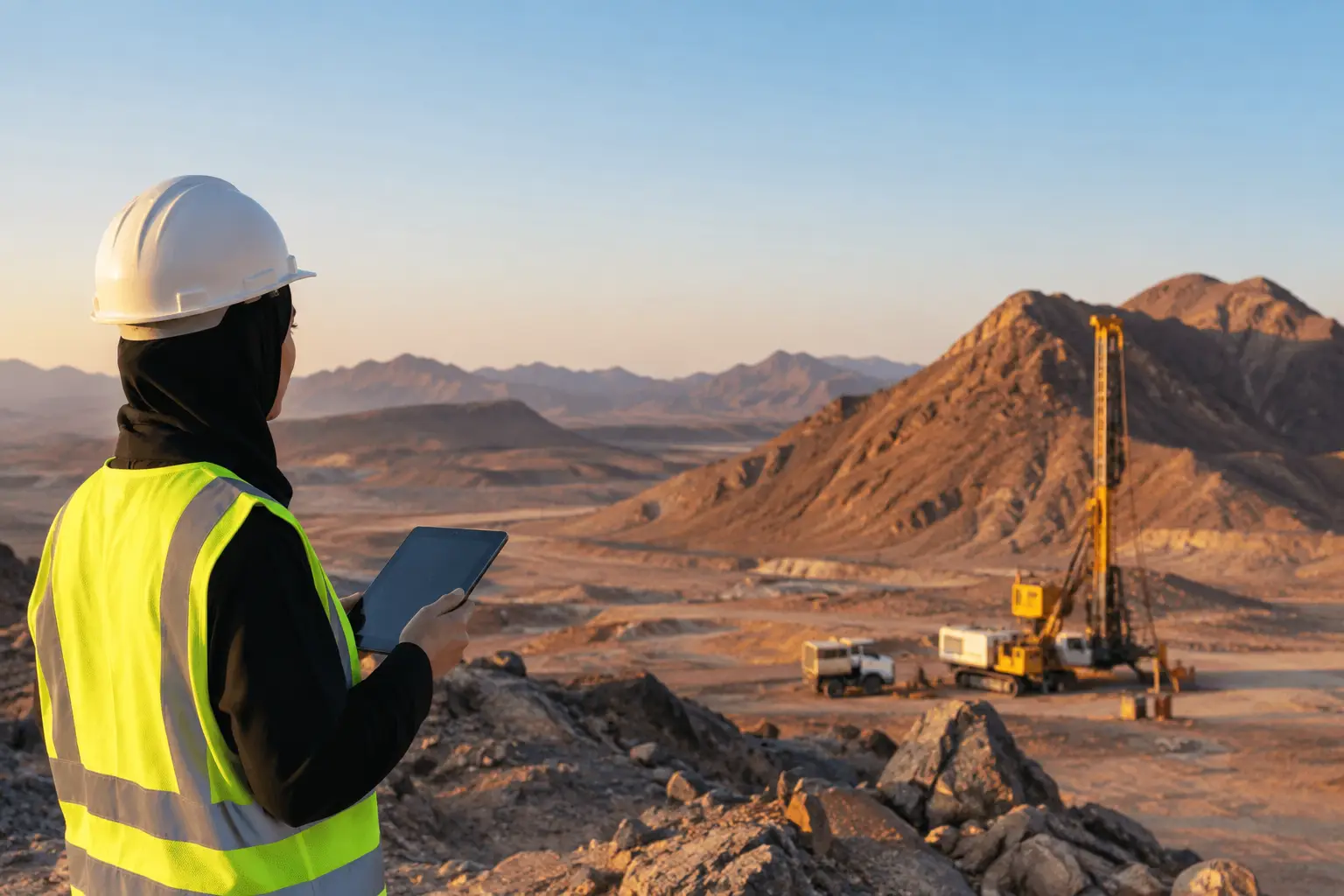
For a regional groundwater or mineral program, EM may establish conductive and resistive domains over a broad area. Selected anomalies can then be tested with ERT profiles, magnetic data, satellite interpretation, field mapping, and boreholes. This sequence preserves coverage speed while adding local depth control where it has the highest decision value.
For an infrastructure alignment, the sequence may reverse. ERT can characterize subsurface variation at crossings, structures, and high-consequence sections, while EM provides efficient corridor-wide screening for conductive utilities, disturbed ground, or salinity trends. The appropriate order depends on whether the primary risk is regional uncertainty or a localized engineering constraint.
Data Quality Determines Whether Results Are Usable
Neither method is immune to non-geological interference. EM data can be affected by fences, pipelines, vehicles, powerlines, rail systems, and surface metal. ERT data can be degraded by poor electrode contact, cable faults, electrical noise, topographic effects, and inappropriate inversion settings. These issues are manageable only when acquisition and processing are controlled.
A decision-grade program should document instrument calibration, positioning accuracy, line spacing, sensor height or electrode geometry, repeat measurements, noise rejection, terrain correction, inversion methodology, and interpretation assumptions. Field observations, photographs, known infrastructure, borehole records, and geological mapping should be incorporated as constraints, not appended after interpretation.
For complex sites, multi-sensor fusion is often more reliable than a single-method conclusion. Magnetic data can help separate ferrous cultural sources from geological conductors. LiDAR and photogrammetry can improve terrain correction and line planning. Ground truth from pits, wells, and boreholes provides the cross-validation needed to convert a geophysical anomaly into a defensible target.
Selecting the Method That Fits the Project
Choose EM when coverage rate, low ground disturbance, and conductivity mapping are the priority. Choose resistivity when the project requires focused subsurface sections, controlled geometry, and stronger local depth interpretation. Choose both when a high-value decision depends on separating broad regional patterns from site-specific conditions.
For enterprise programs, the preferred outcome is not more geophysical data. It is a calibrated, auditable interpretation that reduces uncertainty before capital is committed. Air Solutions approaches EM and resistivity planning from that operational standard: align the sensing method to the target, verify the response against independent evidence, and deliver a technical basis that engineering, exploration, and procurement teams can act on with confidence.