A GPR survey is often commissioned after a project has already encountered uncertainty: an unmarked utility alignment, suspected slab void, unexplained pavement failure, or a planned excavation with incomplete records. At that stage, the objective is not simply to produce a radar image. It is to establish a defensible subsurface interpretation that allows engineers, asset owners, and contractors to make a safer decision before mobilizing labor and equipment.
Ground-penetrating radar provides non-destructive, high-resolution sensing of near-surface conditions. Its value is strongest when the survey design, positioning, calibration, data processing, and interpretation are controlled as one technical workflow. A poorly planned scan can create false confidence. A calibrated GPR program, correlated with records and verified where necessary, can materially reduce excavation risk, rework, and schedule exposure.
What GPR Measures Below the Surface
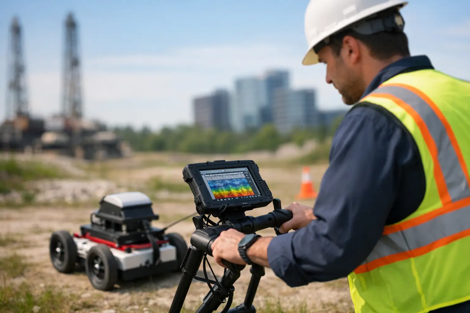
GPR transmits electromagnetic energy into the ground or a structure and records reflections created where material properties change. These changes may occur at the boundary between soil layers, around a buried pipe, at reinforcing steel, within a concrete defect, or across an air-filled void. The response is presented as a radar profile, commonly called a radargram, which must then be interpreted in its spatial and engineering context.
The method does not directly identify every buried object by name, size, or depth. It identifies contrasts in dielectric properties. A metallic utility, for example, may generate a strong reflection, while a non-metallic pipe can be visible because its material and surrounding backfill differ from the host soil. Hyperbolic reflection patterns can indicate discrete targets, but target classification requires trained interpretation, systematic line spacing, and supporting evidence.
Depth conversion is equally important. GPR records travel time, not depth. Converting that travel time to depth requires an estimate of signal velocity through the surveyed material. Velocity can be derived from known features, hyperbola fitting, common-midpoint methods, cores, test pits, or other verification controls. Without this step, reported depths can carry uncertainty that is unacceptable for design or excavation decisions.
GPR Performance Depends on Ground Conditions
GPR is powerful, but it is not universal. Signal penetration and target resolution are governed by antenna frequency, material conductivity, moisture content, salinity, clay fraction, and the geometry of the target. Higher-frequency antennas provide finer resolution in shallow investigations, particularly for concrete and pavement. Lower-frequency systems can investigate deeper conditions, but with reduced detail.
Dry, resistive sand and competent rock can provide favorable penetration conditions, making GPR particularly useful for selected desert infrastructure, utility, and geotechnical applications. Conversely, conductive clay, saline groundwater, saturated fine-grained soils, and reinforced concrete with dense steel can attenuate radar energy rapidly. In these environments, the absence of a reflection should never be treated as proof that no target exists.
This is why project requirements should define the decision to be supported, rather than merely requesting a generic scan. Locating the upper reinforcement mat in a bridge deck, mapping shallow utilities before trenching, and investigating a possible subsurface void are different problems. They require different antenna selections, acquisition geometries, survey grids, depth expectations, and acceptance criteria.
A Controlled GPR Survey Workflow
Decision-grade results begin before field deployment. Available utility drawings, as-built records, prior geotechnical information, site constraints, and planned construction activities should be reviewed to define the investigation area and the consequence of an incorrect interpretation. This risk-based planning determines line spacing, survey orientation, control requirements, and the appropriate level of verification.
Acquisition Design and Position Control
Survey lines must be close enough to detect targets between traverses. For utility corridor work, orthogonal passes can help distinguish linear features from isolated anomalies and clarify alignment. For concrete investigations, a tightly spaced grid may be required to map reinforcement, conduits, delamination indicators, or thickness variation across an entire slab or deck.
Positioning should be traceable to a defined project coordinate system. Depending on the application, this may involve survey control, total station tracking, GNSS, encoder-based distance measurement, or precisely established local grids. Data without reliable spatial control cannot be confidently integrated into design drawings, GIS environments, or construction set-out plans.
Field teams should also document site conditions that affect interpretation: wet areas, visible surface repairs, access limitations, interference sources, and locations where the antenna could not maintain consistent ground coupling. These observations are part of the evidence chain, not administrative detail.
Processing, Interpretation, and QA/QC
Raw GPR data requires processing to improve signal clarity while preserving genuine subsurface responses. Typical steps may include time-zero correction, background removal, gain adjustment, filtering, velocity analysis, migration, and depth conversion. Processing parameters should be documented and proportionate to the project objective. Over-processing can suppress meaningful anomalies or create visual artifacts that appear more certain than the underlying data supports.
Interpretation should differentiate between observed responses and inferred features. A deliverable may identify a probable utility, a possible void-related anomaly, or an area requiring intrusive confirmation. That language is not a limitation in reporting. It is disciplined risk communication.
A technically credible report records equipment configuration, antenna frequency, survey coverage, coordinate reference, processing methodology, depth assumptions, limitations, and confidence levels. Where results are integrated with electromagnetic locating, LiDAR, photogrammetry, GIS records, or test-pit findings, the basis of correlation should be clear and fully auditable.
Where GPR Creates Operational Value
For utility detection, GPR can identify both metallic and selected non-metallic services that may not be detected through electromagnetic locating alone. Its strongest role is often as part of a multi-method utility investigation, particularly where records are incomplete or congested corridors require cross-validation. It can support route planning, excavation permits, clash avoidance, and targeted potholing.
In concrete assessment, GPR can map reinforcing bar layouts, post-tension tendons, embedded conduits, slab thickness, and selected zones of potential deterioration. The method supports safer coring, cutting, anchoring, and rehabilitation planning. However, dense reinforcement, high moisture, and complex structural geometry can limit interpretation, so survey results should be reviewed against structural drawings and field verification plans.
For roads, airfields, and industrial yards, GPR can help investigate layer interfaces, detect localized anomalies, and target areas for follow-up testing. It does not replace geotechnical drilling or laboratory analysis when material classification and engineering properties are required. Instead, it improves the efficiency of those intrusive programs by defining where detailed investigation is most valuable.
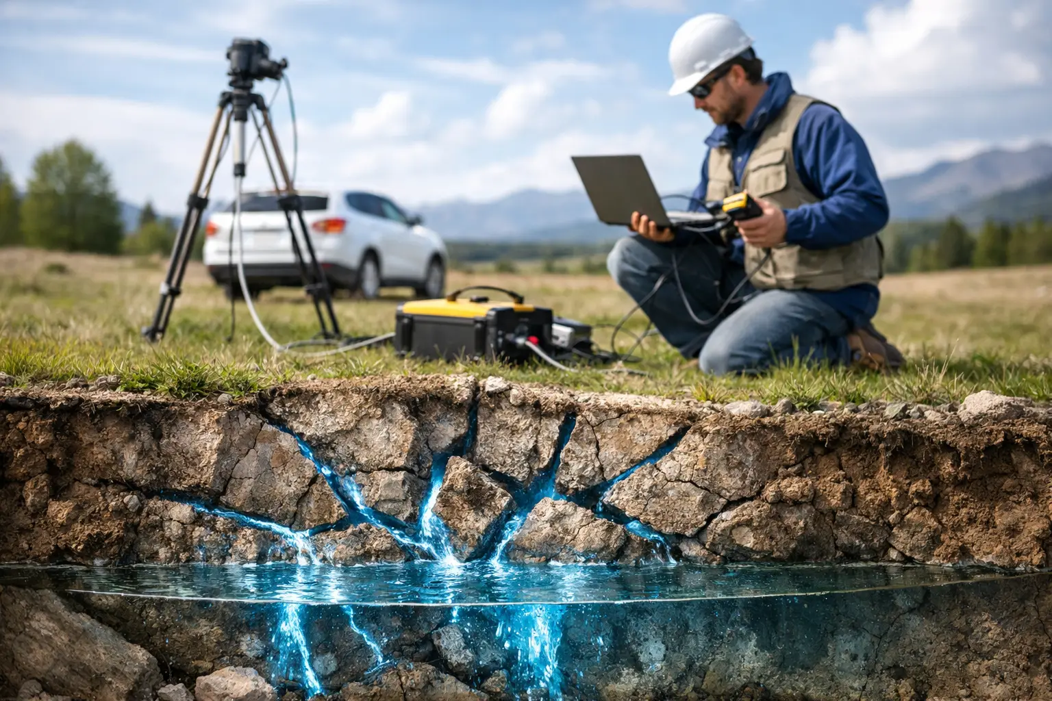
GPR also supports void and subsidence risk screening beneath slabs, pavements, and selected embankment settings. A radar anomaly may indicate a void, disturbed ground, moisture contrast, or buried debris. Confirmation may require drilling, coring, camera inspection, electrical methods, or other targeted checks. The appropriate response depends on the consequence of failure and the confidence needed for the next project decision.
Why GPR Should Be Integrated, Not Isolated
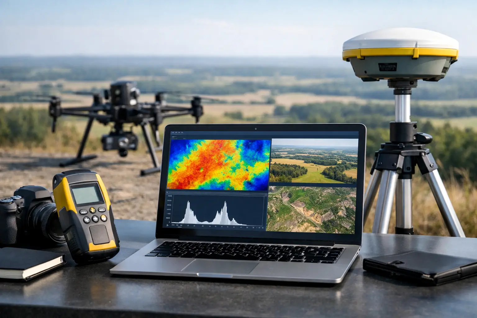
No single sensor can fully characterize a complex subsurface environment. GPR performs best when it is deployed within an integrated survey strategy. Electromagnetic utility locating can strengthen identification of energized or conductive services. Topographic mapping can connect anomalies to drainage, settlement, and surface geometry. Aerial imagery and GIS can establish broader asset context. Test pits and boreholes provide direct confirmation at critical points.
This integrated approach is especially relevant for high-value industrial and infrastructure sites, where a missed utility or unverified anomaly can affect safety, schedule, insurance exposure, and contractor performance. The commercial question is not whether a survey produces data. It is whether the resulting interpretation reduces uncertainty enough to change the quality of a decision.
Air Solutions applies this principle through controlled acquisition, documented QA/QC, and interpreted deliverables designed for engineering and operational teams. The required level of investigation is scaled to the asset, the ground conditions, and the consequences of being wrong.
Before authorizing excavation, coring, demolition, or route selection, define the subsurface question in measurable terms. A GPR survey becomes far more valuable when it is commissioned as evidence for a specific decision, with clear confidence thresholds and a verification path for the anomalies that matter most.